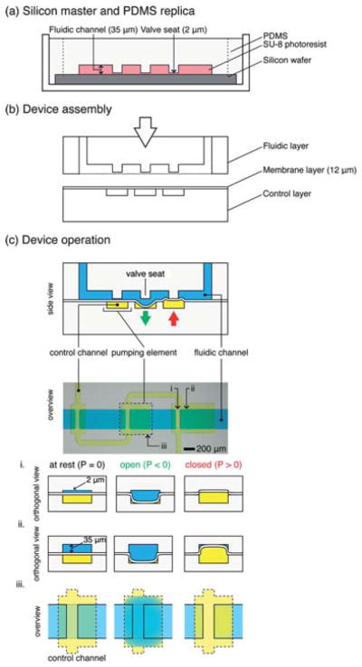
Fig. 1. Overview of “single-stroke” micropump (SSμP) fabrication and operation.

(a) Fabrication of the PDMS micropump by soft lithography. Silicon masters (not shown) of the fluidic layer and control layer are fabricated by photolithography using SU-8 negative photoresist; replica layers are made by pouring PDMS polymer (10: 1 w/w, pre-polymer: crosslinker) onto silanized masters. (b) Assembly of fluidic layer, control layer, and PDMS membrane by O2-plasma bonding. Thin PDMS membrane is spun onto clean, silanized silicon wafers, cured, and subsequently bonded to the control layer after O2-plasma exposure; access ports are opened in the fluidic layer and bonded under vacuum to the control layer and thin membrane. (c) Top half: Schematic representation and stereomicrograph of a SSμP; bottom half: operation schematic of a microvalve. Orthogonal cross-section of the microvalve at the valve seat (i) and above the pumping element (ii) is depicted along with the overview of the microvalve (iii). At rest, the valve is partially open due to the gap between the valve seat and thin membrane in the fluidic channel; in this “leaky state”, the microvalve functions as a flow resistor that restricts large particles and reduces fluid flow. When positive pressure is applied, the thin membrane deflects upward, pressing against the raised valve seat, effectively closing the channel; however, only the raised valve seat is closed completely while the region with regular channel height is not, due to the rectangular geometry of the channel. The volume displaced by the deflecting thin membrane into the 35 μm tall region of the channel provides the bulk of fluid flow in pumping operations. When vacuum is applied, the thin membrane deflects downward, revealing a large opening for fluid passage beneath the valve seat; the vacuum stroke speeds up air evacuation from the pressurized state and also enables greater fluid filling.
