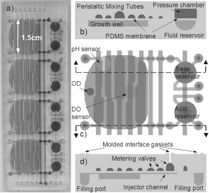
Figure 7.

Pneumatic peristaltic 100 µL microbioreactor system presented by Lee et al. (2006). a: Four reactor module image showing common pneumatic channels. b: Bioreactor cross-section illustrating pressure actuated channels for mixing, and pressurized acid/base reservoir. c: Top view of single reactor with sensors indicated, and peristalsis layout. d: Cross-section showing metering valves for releasing acid/base solution. Figure reproduced with permission from Lee et al. (2006) (Copyright 2006 Royal Society of Chemistry).
