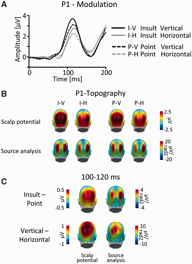
Fig. 3.
P1 component. (A) Illustration of the ERP waveforms for a right parieto-occipital sensor (EGI #152; Fig. 4). (B) Scalp topography maps (top) and according source analysis (bottom) for all picture categories in the time window 100–120 ms. (C) Scalp difference maps (vertical–horizontal and Insult–Point; left) and according source analysis (right) in the time window 100–120 ms. Please note the different scales.

