
Figure 2. Definition of the four glenoid component positioning parameters.
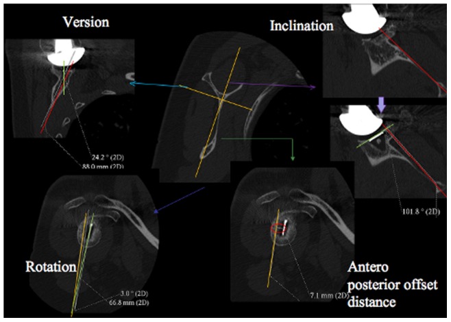
: version (top left) is the angle between the green line (i.e. the orientation of the glenoid component surface) and the red line (i.e. the orientation of the scapula plane); inclination (top right) was measured from the orientation of green line (i.e. the superior-inferior line of the glenoid component) and the red line (i.e. the orientation of the supraspinatus fossa line (SFL)); rotation (bottom left) is the angle between the orange line (i.e. the orientation of the scapula plane) and the green line (i.e. the superior-inferior line of the glenoid component); off-set distance(bottom right) was measured as the shortest distance between the white marker in the CT image (i.e. the centre of the glenoid) and the orange line (i.e. the orientation of the scapula plane). The orange lines in the middle image indicate the orientation of the scapula blade used.