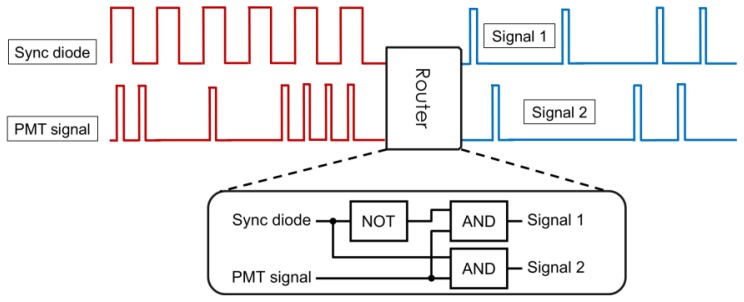
Figure 2.
Schematics of signal demultiplexing. The PMT signal is sorted into demultiplexed channels for each beam based on the signal from the synchronization diode. The router can be implemented directly in programmable counting cards, or as a separate unit consisting of fast electronic logic gates (inset).

