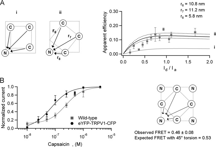
FIGURE 6.
Possible angular torsion between the N- and C-terminal planes. A, FRET between N-terminally eYFP-labeled and C-terminally CFP-labeled subunits. The critical distances are represented in the diagrams as r6, r7, and r8. The gray solid line in the right panel is the prediction for no angular torsion between the terminal planes as shown in (panel i). The only arrangement for the observed FRET corresponds to an approximately 40° rotation between the N- and C-terminal planes as shown in panel ii. B, the assembled double labeled channel with eight fluorescent proteins is activated by capsaicin in a dose-dependent manner (n = 8). The observed FRET in this channel is consistent with a 45° angular torsion between the N- and C-terminal planes. The arrows in the diagram indicate the direction of the energy transfer for one of the four acceptors.

