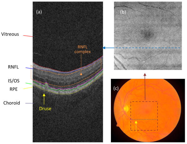
Fig. 1.
(a) Target retinal layers of a cross-sectional SD-OCT image (B-scan). RNFL: retinal nerve fiber layer; IS/OS: photoreceptor inner/outer segments; RPE: retinal pigment epithelium. The location of a druse is indicated with a yellow arrow. The RNFL complex (defined as the region between the inner limiting membrane and outer plexiform layer) is indicated by the orange dotted region. (b) SVP image of the same eye. The dashed blue line indicates the location of the B-scan presented in (a) within the projection image. (c) Color fundus photograph of the same eye. The maroon dashed square indicates the area in the macula present in the SD-OCT scan. The dashed blue line indicates the location of the B-scan presented in (a) within the fundus photograph. The location of the druse clearly seen in (a) is indicated with a yellow arrow.

