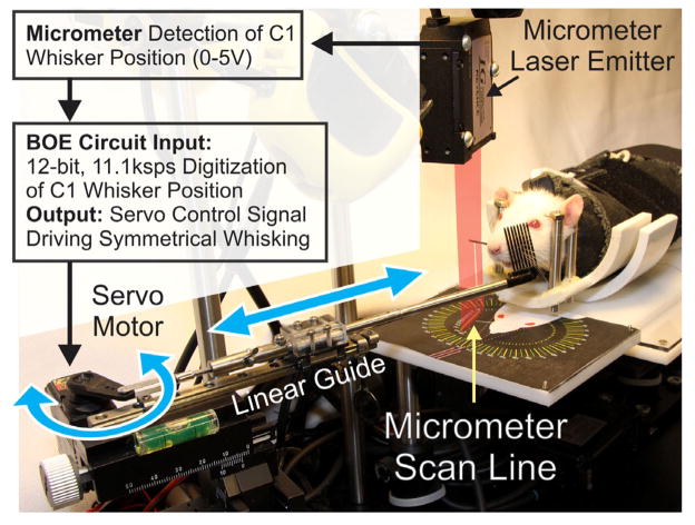
Fig. 4.
Flow diagram of healthy whisking detection on one side leading to robotic assistance of contralateral movement on the recovering side. The marked C1 whisker on the right is shown breaking a superimposed representation of the laser light curtain, causing a shadow that is detected by the micrometer scan line. The detected C1 position is digitized by the BOE circuit, and custom software generates a servo motor control signal that moves the rod holding the whisker comb and generates symmetrical, bilateral whisking. Double-headed arrows show direction of movement for the servo horn and linear guide holding the whisker comb rod.

