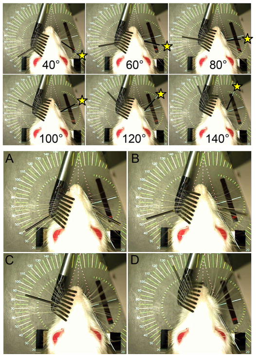
Fig. 5.
Top: Overhead camera view of WA system showing a testing rod on the right (marked with a yellow star) being moved from 40° to 140° and the left-side whiskers being moved by the servo motor mechanism (C1 whisker is marked with a thin black tube) as the system tracks the right-side marker. Bottom: Still video frames captured while the WA system tracked the C1 whisker on the right (intact) and simultaneously drove the paralyzed whiskers on the left in a yoked pattern across the full range of motion (e.g. panels A-D moving from 40° through approximately 140°). The rectangular hole in the platform below the rat (located 1 cm lateral to the right whisker pad) houses the laser micrometer detector which tracks the right C1 whisker position. Figured modified from IEEE Neural Engineering, 2011, pp. 629–633.

