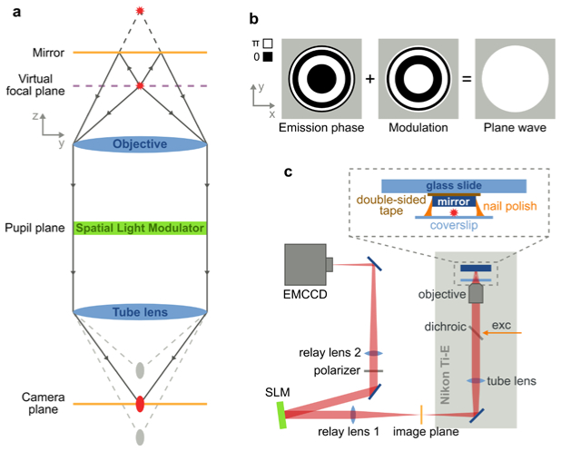
Fig. 1.
Schematic of 4Pi detection with a single-objective and the experimental setup. (a) A fluorophore and its reflection (red stars) are imaged by an infinity corrected microscope (blue), which generates an image and a mirror image of the fluorophore along the optical axis (gray ellipses). Phase modulation in the pupil plane with an SLM (green) can overlay the two images (red ellipse) at the camera plane (orange), creating a virtual focal plane (violet) at the fluorophore position. (b) The emission phase of a fluorophore in front of a mirror at the pupil plane are concentric rings of either 0 or π and is strongly dependent on the distance between fluorophore and mirror. Modulation of this phase with its exact opposite (middle) results in a plane wave (right), which is focused at the camera plane. (c) The experimental setup is based on a Nikon Ti-U microscope with a custom excitation path and a relayed emission path. The SLM is located at the Fourier plane of relay lens 1. The sample is sandwiched between the coverglass and a mirror.

