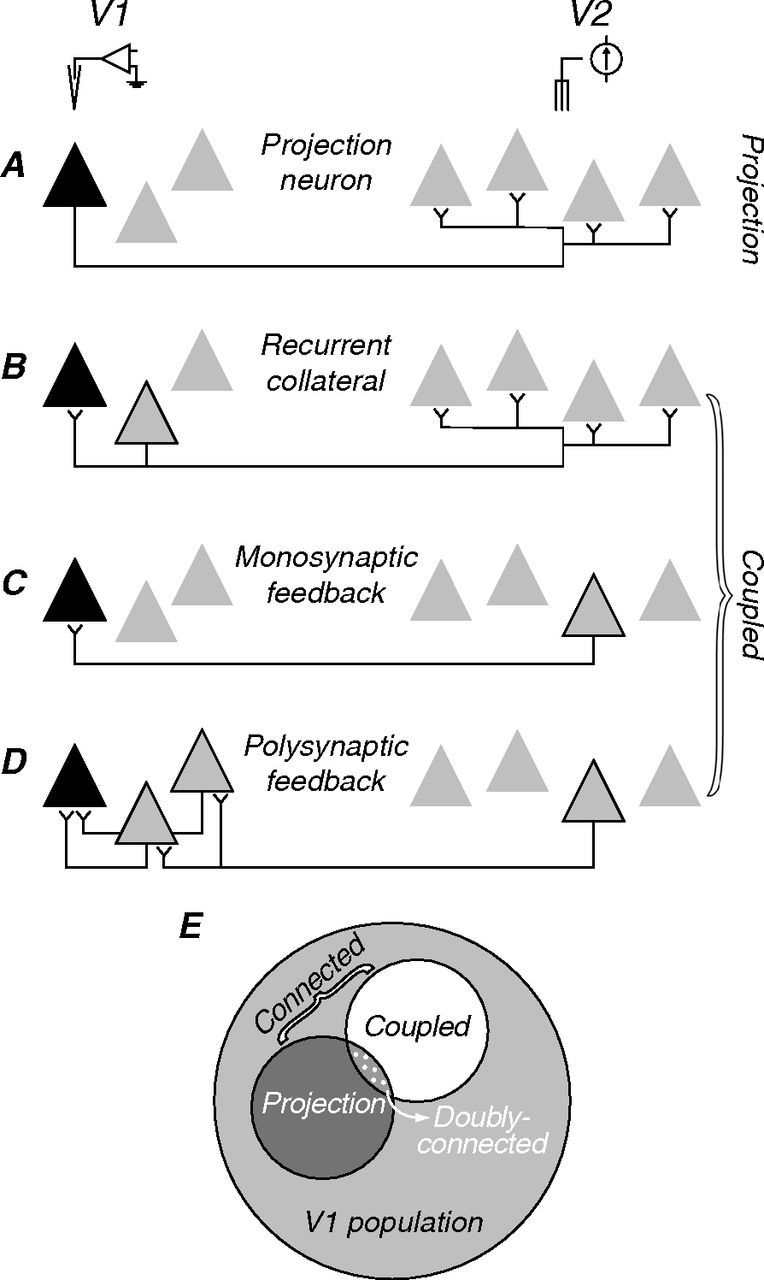
Figure 1.

Possible neuronal circuits linking V1 and V2. A–D, Triangles symbolize hypothetical groups of neurons in V1 (right) and V2 (left). In each panel, black symbols represent the neuron recorded; in B–D, gray symbols with black outlines represent the neurons that relay the electrically elicited spikes. A, Feedforward projection: here, a spontaneous V1 spike would collide with a suitably delayed electrically elicited spike, thus satisfying the collision test. B–D, Other possible circuits in which the electrically elicited spike will not be occluded and the collision test will fail. B, Recurrent collateral of a neighboring projection neuron. C, Monosynaptic feedback projection. D, Polysynaptic feedback connection. Because we cannot distinguish among the circuit arrangements shown in B–D, we classify all connected cells that fail the collision test as “coupled.” E, Schematic showing the relationship of projection and coupled neurons to the larger V1 population. Note that some neurons may be both projection and coupled.
