
Figure 1.
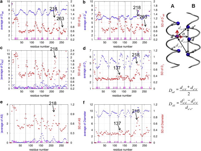
Results of local flexibility analysis of Tm in the absence of F-actin (system 1) using six parameters: (a), (b), (c), (d), AS (e), and diameter (f). For definitions of these parameters, see Methods. The average and SD of the above parameters as a function of the a and d residue positions of Tm are shown as symbols  and
and  , respectively. The long vertical lines mark the center positions of six Ala clusters (A22, A78, A120, A155, A183, and A239). The positions of individual core Ala residues are marked by short dashes. The calculations are based on the last 10 ns of four 20-ns MD trajectories of system 1. (Inset) The hydrophobic interface between chains A and B of the Tm coiled coil is shown. Three core residues in each chain (at the a′, d, and a″ positions) are shown as spheres, and the distances between these residues (, , and ) and the perpendicular distance, , between the d residue and line - are shown by double-headed arrows. The two orthogonal motions (i.e., axial and lateral motion) of the d residue in chain A relative to chain B are highlighted by two bold arrows. To see this figure in color, go online.