
Figure 3.
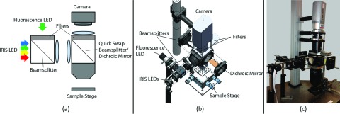
Integrated instrument design. (a) Schematic of the optical layout. For fluorescence, the second beamsplitter is swapped for a dichroic mirror and the emission filters are inserted. (b) Model of instrument with key components labeled. (c) Image of the constructed instrument.