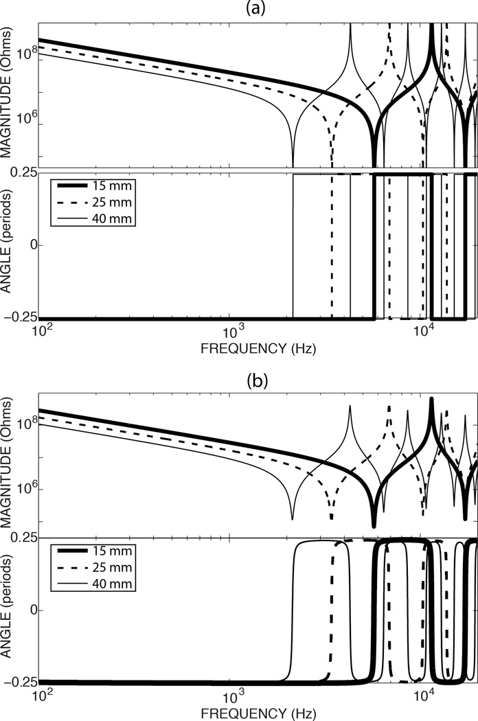
Figure A2.
Magnitude and phase of the impedance of three lossless closed tubes of 15, 25, and 40 mm. The diameter of the tubes is 8 mm. The top panels illustrate the magnitude of the impedance of the tubes; the lower panels illustrate the impedance phase angle. The frequency is coded on the x-axis on a log scale from 100 to 20000 Hz. In (a), which assumes the air and tubes are lossless, the impedances at the tube resonances go to 0 (which is difficult to plot on the log magnitude axis) and the impedance at the anti-resonance frequencies is infinite. In (b) the inclusion of viscous and heat losses introduces small deviations at frequencies less than 100 Hz, limits the infinitely sharp peaks and valleys, and smooths the sudden half-cycle phase changes at the tube resonance and anti-resonances (Lynch, Peake and Rosowski 1984).

