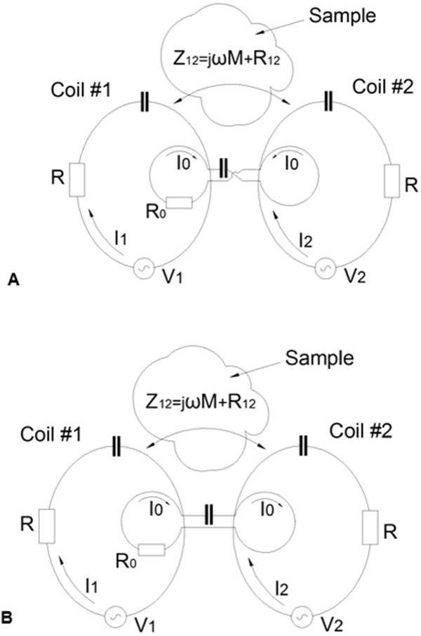
Figure 1.

Schematics demonstrating the general ideas of constructing RID circuits using a “butterfly” (“figure eight”) coil (A) a regular surface coil (B). Two geometrically identical resonant coils #1 and #2 are coupled with their shared impedance Z12 and characterized by the inductance L, and the resistance R, In the presence of the sample the mutual impedance Z12 contains both reactive, jωM, and resistive component, R12. RID circuits shown in A) and B) are characterized by the inductance L0 and the resistance R0.
