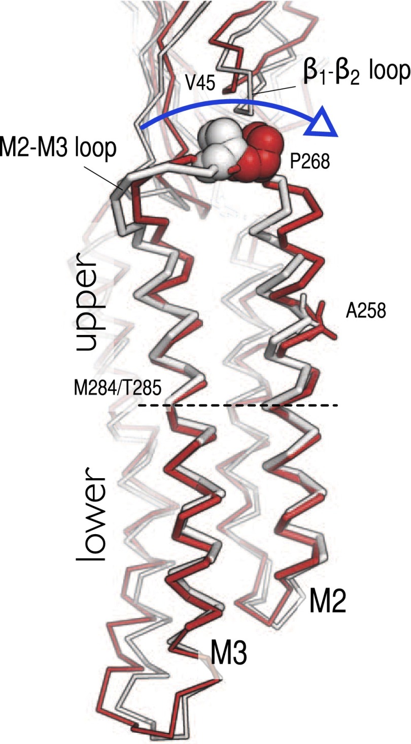
Fig. 4.
The unbending of the M2–M3 group couples the inward displacement of the M2–M3 loop at the EC/TM domain interface to the closing of the ion pore. Snapshots of the M2–M3 group taken before (1 ns) and after (50 ns) the inward displacement of the M2–M3 loop in the A subunit are shown as white and red ribbons, respectively. The side chains of P268 on the M2–M3 loop and A258 on M2 at the constriction point of the ion pore are highlighted by vdW and sticks representations, respectively. The position of the M284 and T285 residues that form a stable kink in the middle of M3 and structurally separates the M2–M3 group into upper and lower regions is also indicated. The comparison shows that the polar untilting of the M2 helices, which couples the repositioning of the interfacial loops to the closing of the channel, is realized through the coordinated unbending of the M2 and M3 helices (see blue arrow). Molecular snapshots are shown after optimal superimposition of the Cα atoms of the TM domain of the pentamer to project out structural changes introduced by twisting of the pLGIC.

