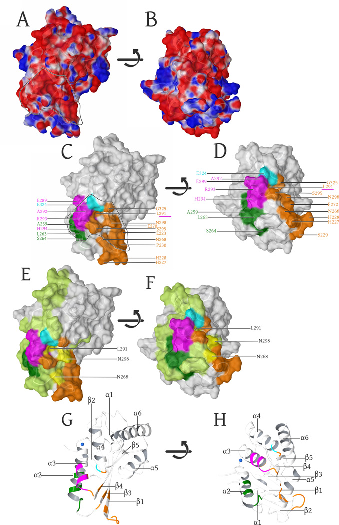
Fig. 5. Surface representation of the A3F-CTD structure.
(A): Surface representation, colored by electrostatic potential (blue is positive, red is negative: − 0.05 -to- +0.05 kcal/mol (Maestro 9/Schrodinger, LLC)). The negatively charged groove region, electrostatically favored to bind the positively charged Vif is delineated by the dashed line and highlights the overlap with known Vif-binding regions in (C).
(B). Same representation as in (A), with the surface rotated +90° (bottom facing out) along the horizontal axis in the image plane.
(C): α3-helix (289–294, magenta) (Smith and Pathak, 2010), the α4 (324, cyan (Albin et al., 2010b), β3-strand (Y269) including part of the α2-helix and the adjacent loop region (L255, F258, C259, I262-S264, dark green) (Kitamura et al., 2012) are known Vif-binding regions that adjoin the β1-β2 (E223, H227-P230), β3(N268, E270), α3(L291, S295), β4(N298) and the α4-β5 (G325) regions (orange) involved in forming the interface. The α3 (L291) residue involved in our intermolecular interface as well as the previously characterized Vif-binding region (Smith and Pathak, 2010) is underlined in magenta.
(D). Same coloring and labels as in (C), with the surface rotated +90° (bottom facing out) along the horizontal axis in the image plane.
(E): Highlights of the complete mutational scan (Kitamura et al., 2012) of A3C (light green) projected onto our A3F-CTD structure. The regions that have were shown to be important for HIV-1 Vif binding are highlighted as above in (C). Yellow highlights and labels show the three residues that overlap between our interface and the A3C mutational scan not tested in A3F by (Kitamura et al., 2012), However L291 was independently probed (Smith and Pathak, 2010)) and found to be important in A3F binding to Vif.
(F). Same coloring and labels as in (E), with the surface rotated +90° (bottom facing out) along the horizontal axis in the image plane.
(G): Secondary structure of these views labeled for reference orientation, with the highlights colored as per (C).
(H). Same coloring and labels as in (G), with the structure rotated +90° (bottom facing out) along the horizontal axis in the image plane.

