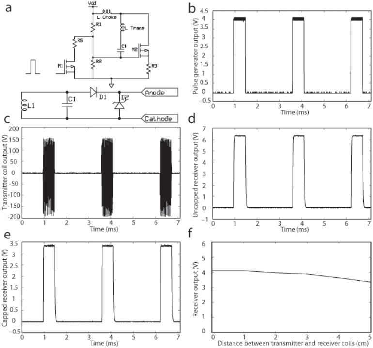
Figure 3. Layout of the wireless-powered pacemaker.
(a) Circuit layout of transmitter (top) and receiver (bottom). (b) Pulsed input into transmitter from pulse generator. (c) Output from transmitter. (d) Uncapped output from receiver. (e) Capped output from receiver. (f) Receiver output decreases minimally up to 5 cm from the transmitter coil. See text for further details.

