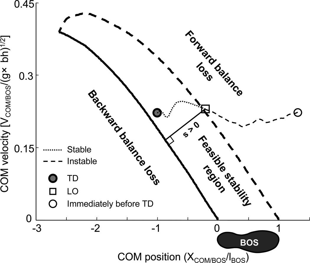
Fig. 1.
Schematic illustration of the feasible stability region (FSR), which is enclosed by two boundaries: the limits of stability (LOS) against backward balance loss (the thick solid line) and those against forward balance loss (the thick dashed line). The stability measurement (s, the length of the thin solid line) indicates the magnitude of the instantaneous stability of the center of mass (COM) against backward balance loss, and is defined as the shortest distance from the instantaneous COM motion state (i.e., the x-coordinates represents the COM anteroposterior position and the positive y-coordinates indicates its forward velocity) to the corresponding LOS. The regular walking consists of alteration of stability recovery (i.e., the motion state trajectory is either moving towards or staying inside the FSR as the thin dotted line) followed by an instable period (i.e., it is moving outside and away from the FSR as depicted by the thin dashed line) progressing from the touchdown (TD, thick filled circle), through the contralateral foot liftoff (LO, thin square), and immediately prior to the contralateral foot TD (thin circle). Position and velocity of the COM relative to the base of support (BOS) are dimensionless as a fraction of lBOS and , respectively, where lBOS represents the foot length, g is gravitational acceleration, and bh the body height. Please note, a single foot was used as the BOS in the stability calculation for the illustration purpose of keeping the COM motion state trajectory continuous during each step cycle.

