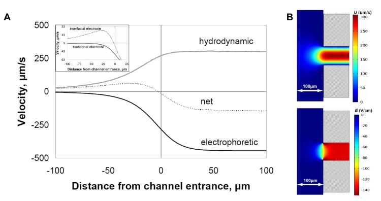
Figure 3.
(A) Simulation showing the principle of electrophoretic exclusion at a channel entrance with an electrode exactly at the reservoir-channel interface. The central dashed line represents the net velocity resulting from electrophoretic velocity opposing bulk fluid velocity. (Inset) The net velocity with an interfacial electrode configuration, as described in A, compared to the net velocity profile of a traditional CE configuration, where no interfacial electrode is present. All plots reflect centerline values. (B) Surface plot simulations of fluid velocity, U, from 0.68 nL/s applied flow rate and electric field, E, from 700 V applied potential at a converging channel entrance with interfacial electrode.

