

Abstract
In modern hospitals, patients are treated using a wide array of medical devices that are increasingly interacting with each other over the network, thus offering a perfect example of a cyber-physical system. We study the safety of a medical device system for the physiologic closed-loop control of drug infusion. The main contribution of the paper is the verification approach for the safety properties of closed-loop medical device systems. We demonstrate, using a case study, that the approach can be applied to a system of clinical importance. Our method combines simulation-based analysis of a detailed model of the system that contains continuous patient dynamics with model checking of a more abstract timed automata model. We show that the relationship between the two models preserves the crucial aspect of the timing behavior that ensures the conservativeness of the safety analysis. We also describe system design that can provide open-loop safety under network failure.
Keywords: closed-loop medical systems, model-based development, safety analysis
I. Introduction
CLINICAL scenarios for critical care patients often involve large numbers of medical devices. Some of these devices, such as bedside monitors, provide vital information about the state of the patient. Other devices, for example, infusion pumps, provide treatment. That is, they affect the state of the patient, for example, by infusing medication. Medical device systems, considered together with the patient and caregivers, represent an important class of cyber-physical systems. Patient safety is the primary concern in such systems, yet reasoning about patient safety is very difficult because of insufficient understanding of the dynamics of human body response to treatment. Human errors, another important source of patient safety problems, are also difficult to reason about in the framework of conventional embedded system development.
It is natural to view a clinical scenario as a control system, in which the patient is a plant, bedside monitors are sensors and infusion pumps are actuators. Traditionally, caregivers perform the role of the controller in such a system. This means that the caregiver needs to continuously monitor all sensor devices and apply appropriate treatment. The large number of devices to monitor and control makes the job of the caregiver very difficult. On top of that, a caregiver is typically responsible for several patients. An emergency may divert the caregiver’s attention elsewhere, making him or her miss an important event. As a result, patient safety may suffer. Multiple such occurrences are documented in the clinical literature.
The human caregiver will always play an indispensable part of most clinical scenarios. However, in many cases automatic controllers can play important roles, reducing the burden on the caregiver and avoiding the possibility of human errors. A number of such cases has been documented in the ASTM standard for the Integrated Clinical Environment [2], developed by the Medical Device Plug-and-Play Interoperability program(mdpnp.org) [3]. Although many medical devices today have network interfaces and can send sensed data across the network, few can be controlled remotely. Vendors of medical equipment continue to stay away from closed-loop scenarios.
The rationale is that it is difficult to reason about patient safety in closed-loop scenarios. Such reasoning is necessary for medical devices, which have to be approved for use by government regulators who assess their safety and effectiveness. A particular challenge arises from the complexity of a complex interplay between the continuous dynamics of the patient reaction to treatment and the discrete nature of the controller and communication network. The dynamics of the patient body is not well understood and exhibits parametric uncertainty and high variability between different patients.
To overcome this difficulty, we explore a model-driven approach that allows us to prove safety properties of devices on the modeling level and ensures that abstract models used in the verification process are sound with respect to the actual dynamics of the system. Both the abstract, formal model and the detailed, informal model are needed in the process of verification, validation, and regulatory approval of closed-loop medical device systems. On the one hand, formal models allow us to exhaustively explore the possible behaviors of the system and prove its safety. On the other hand, detailed models allow us to use high-fidelity simulation that take real system dynamics into account. Both kinds of results can be used to make the case for regulatory approval.
We start with a detailed model of the system in Simulink. The model contains a patient model that reflects continuous pharmacokinetic dynamics of drug absorption by the patient body. To reflect the variation between different patient populations, the patient model incorporates uncertainty in the values of its parameters. The Simulink model enables high-fidelity simulations of the system in various scenarios. Yet, currently there are no tools supporting the verification of hybrid systems (i.e., systems consisted of both discrete-time components and continuous-time dynamics) modeled in Simulink that are both nondeterministic and with uncertain parameters. Most existing tools for Simulink are limited to testing-based analysis that does not guarantee the coverage of parameter space.
In order to prove safety of the system, we express the safety property as a timing relationship between components of the system. We then model the system using the formalism of timed automata [4] in the UPPAAL tool [5]. The model abstracts away continuous dynamics of the system, replacing it with timing constraints. The values for the timing constraints are obtained from the continuous dynamics of system components using the detailed model in Simulink. It is necessary to guarantee that the patient model in UPPAAL over-approximates the patient’s dynamics with respect to the utilized control algorithm. For that, we present a procedure that utilizes convex optimization to calculate an upper bound on critical timing values for a linear time-invariant (LTI) model with uncertain parameters and show that behaviors of the UPPAAL model is always within this bound.
There is a need to develop a methodology for the analysis of safety properties of closed-loop medical device systems [6]. In this paper we present a case-study focused on a system of clinical importance. In the case study, we prove that the system is safe under a set of assumptions. We then demonstrate that a violation of these assumptions – for example, by a more realistic fault model – can make the system unsafe. Finally, we propose a solution to restore the safety of the system under the new fault model. The approach presented in this paper is intended to serve as a reference point, a step toward a model-based methodology for safety analysis of closed-loop medical device systems.
The rest of the paper is organized as follows. Section II introduces the medical case study and presents the system architecture that we used to describe our approach. Section III explains the use of Simulink models of the system to analyze safety with no failure assumption. It also describes a procedure used to translate safety requirements into timing constraints in cases where system is modeled as a continuous-time LTI system with uncertain parameters. Section IV describes the UPPAAL models of the system and safety properties we have verified. Section V proposes modifications to the system to deal with failures and provides an argument that the new system guarantees open-loop safety. The last section summarizes the paper and identifies the future work.
II. Case Study
In this section, we describe a case study that represents one of the MD PnP interoperability clinical scenarios [2]. In the past, we have built a demonstration of this scenario [7]. Several variants of this system have been presented at the American Society of Anesthesiologists annual meeting in 2007, where it won first place in the scientific exhibits, at the 2008 HIMMS (Healthcare Information and Management Systems Society) Congress, and at the 2008 CIMIT Innovation Congress.
We have built the system according to the Integrated Clinical Environment (ICE) architecture, developed by the MD PnP project. Figure 1 shows the main components of an ICE-compliant system. The patient and caregiver are the human elements of the system. The Supervisor is the computer system that runs the control algorithm. Medical devices are connected, through adapters where necessary, to the Network Controller, which keeps track of connected devices and their capabilities. The Data Logger records pertinent network traffic for later forensic analysis and external networks such as the hospital information system are connected through an external interface. In our case study, we did not model the data logger since it does not affect our runtime safety analysis.
Fig. 1.

MD PnP Architecture with Patient-in-the-Loop Automatic Control.
A. Clinical Use Case
The selected scenario involves a patient connected to a patient-controlled analgesia (PCA) infusion pump. PCA infusion pumps are commonly used to deliver opioids for pain management, for instance after surgery. Patients have very different reactions to the medications and require very different dosages and delivery schedules. PCA pumps give the patient a button to press to request a dose when they decide they want it rather than using a schedule fixed by a caregiver. Some patients may decide they prefer a higher level of pain to the nausea the drugs may cause and can press the button less often, while patients who need a higher dose can press it more often.
A major problem with opioid medications in general is that an excessive dose, or overdose, can cause respiratory failure. A properly programmed PCA system should not allow an overdose because it is programmed with limits on the number of doses it will deliver, regardless of how often the button is pushed. However, this safety mechanism is not sufficient to protect all patients. Some patients still receive overdoses if the pump is misprogrammed, if the pump programmer overestimates the maximum dose a patient can receive, if the wrong concentration of drug is loaded into the pump, or if someone other than the patient presses the button (PCA-by-proxy), among other causes. PCA pumps have been involved in a large number of adverse events [8], and existing safeguards such as drug libraries and programmable limits are not adequate to address all the scenarios seen in clinical practice [9].
The system we are considering aims to improve patient safety in such scenarios by introducing a supervisor that monitors patient data for the early signs of respiratory failure and can stop the infusion and sound an alarm if the patient experiences an adverse event. We use a pulse oximeter device that receives physiological signals from a clip on the patient’s finger and processes them to calculate heart rate and SpO2 outputs, where SpO2 is the measure of blood oxygenation. Note that, at the time of writing, there are no PCA pumps on the market that are capable of being remotely controlled. In the demonstration system, we used the PCA pump prototype we have built during the Generic Infusion Pump project [10].
B. System Architecture
Figure 2 shows the components of the PCA safety system. The system components are described below. Figure 3 shows the devices and essential data flow in this control loop. In the case-study pulse oximeter acts as the Monitoring System from Figure 2. It receives physiological signals from the patient and processes them to produce heart rate and SpO2 outputs. The Supervisor gets these outputs and makes a control decision, possibly sending a stop signal to the PCA Pump. Unless it is stopped by the Supervisor, the PCA pump delivers a drug to the patient at its programmed rate that corresponds to the selected operating mode. The patient model gets the drug rate as an input and updates the drug level in the patient’s body. This in turn influences the physiological output signals through a drug absorption function.
Fig. 2.

Hardware for PCA Demo System.
Fig. 3.

PCA System Control Loop.
1) PCA Infusion Pump
The PCA pump in the case study operates in the following way. Before operation, the pump is programmed by the caregiver, who sets the pump’s operating mode, normal rate of infusion, the increased rate of a bolus, and bolus duration. Some PCA pumps also can be programmed to limit the total amount of drug to be infused. Once programmed and started, the pump delivers the drug at the normal rate until it is stopped or the bolus button is pressed. From that moment, it delivers drug at the bolus rate for the specified duration and then returns to the normal rate.
The pump is equipped with a number of built-in sensors that detect internal malfunctions such as the presence of air in the tubes that deliver the drug. When a problem is detected, the pump is stopped. We do not consider such malfunctions in this case study and do not represent the built-in alarm mechanism.
Finally, the pump is equipped with a network interface, which allows the pump to transmit its status across the network to other devices such as the logger. For the purpose of our scenario, we assume that the network interface allows the pump to accept control signals. A stop control signal will set the current infusion rate to zero, while the start signal will set the normal infusion rate (regardless of the state of the pump before it was stopped).
2) Monitoring System
Patients using a PCA pump are usually also attached to patient monitors that record the patient’s EKG, blood pressure, respiratory rate, and SpO2. These monitors sound alarms if the measured values are outside thresholds set by the caregivers, but do not stop the infusion. Thus, the patient continues to receive more of an overdose while the caregiver responds, assesses the patient, and if a real problem occurred, finally stops the pump.
In this study, we look at using SpO2 and heart rate measurements as the basis for a physiologic closed-loop control system that can stop the PCA pump and halt the dose of opioid while sounding an alarm if respiratory distress is detected. Both of these measurements can be produced by a device called Pulse Oximeter. This device is equipped with a finger clip sensor that shines two wavelengths of light through the patient’s finger. The measured light intensity reflects the blood oxygen content, which can change rapidly.
The pulse oximeter samples the patient’s SpO2 at regular intervals, processes them, and outputs an averaged result [11]. It calculates the average using a variable-sized sliding window. The window size varies with the last output value. The reason for changing the window size is that a smaller sample size gives faster, but potentially less accurate results. When SpO2 values are low, quick response is more important than filtering out transient noise. When SpO2 is high, increasing the window size helps to filter out transient low values at the expense of less frequent updates. Since the samples are at regular intervals and a varying number of samples are used to calculate the output, the output is updated irregularly. The size of the sliding window used in the case study is determined using a simple table shown in Table I. Note that this table does not reflect the details of any real implementation but rather attempts to capture the essential behavior of a typical pulse oximeter.
TABLE I.
Sliding Window Size for Pulse Oximeter
| last output value | 97 - 100 | 94 - 96 | 90 - 93 | 85 - 89 | < 85 |
| new window size | 10 | 8 | 7 | 6 | 4 |
3) Caregiver Model
The caregiver in this system programs the PCA pump and reacts to alarms. The control system is closed loop, so no intervention by the caregiver is necessary to stop the infusion when a problem is detected. The caregiver can react to restart the system if it has stopped in reaction to a false alarm, or when a problem such as a slipped patient sensor is fixed.
4) Patient Model
To model the Patient we use a pharmacokinetic patient model for intravenous delivery of anesthetic drugs presented in [12] (module 12). The model utilizes a common 3-compartment model to describe the changes in drug concentration in blood and tissue. The patient is described as a continuous-time LTI system with a state space representation:
| (1) |
where Ci, i ∈ {1, 2, 3} is the drug concentration in the ith compartment, I is the mass infusion rate (in mass/unit of time) of the drug, kij are patient specific constants and V1 is the volume of the blood plasma compartment. Since compartment 1 presents blood plasma, its concentration is mapped into the drug level concentration dl as in (1).
Using the above model, we represent the instantaneous level of medication in the patient’s body as a single variable dl. This variable is linked to the patient’s heart rate and SpO2 by the drug absorption function, which represents how the patient reacts to the dose received over time. Using dl value, the state space of the patient is partitioned into three regions: in pain (under-medicated), pain-controlled (adequate medication), or over-medicated. These regions, shown in Figure 4, are defined as follows:
The Safe region is defined as the region where the Patient’s readings are below some predefined threshold values that guarantee that Patient’s vitals are not endangered.
If the patient is over-medicated to the point that he or she starts experiencing respiratory distress, we consider it an overdose. Thus, we define the Critical region where Patient’s life is in danger or there is a chance that irreparable damage can occur. The overdose condition is referred as border of the Critical region.
The Alarming region defined as the region where Patient’s vitals are not endangered but there is a reasonable concern that the Patient can be forced to the Critical region.
Fig. 4.

Regions of Patient’s conditions.
Any treatment needs to make sure that the patient stays out of the critical region, and we use this requirement as the main safety property of the system that needs to be ensured. In this case study, since the drug level is estimated from the patient’s SpO2 and heart rate, we defined the boundary of the Critical region in terms of these values and set it to for SpO2 (and for heart rate), a clear indication of respiratory failure.
It is worth noting here that some patients react very quickly to a drug dose, while others react more slowly. Furthermore, a mapping between the drug level on one side and measured SpO2 level and heart rate is also patient specific. Therefore, by adjusting this function, we can tune the model to different patient types. However, in all these cases patient reaction to drug can be described as in (1), where patient specific coefficients belong to predefined regions and fully determine the patient’s behavior.
To analyze the dynamics of the patient’s pharmacokinetic model, we have designed the system model in Simulink (the model is described in next section). This enables simulation and analysis of the system’s behavior under different scenarios.
5) Supervisor
The supervisor is a running program in the system that communicates with other devices and executes clinical application scripts (CAS’s). A CAS is a script that implements a particular clinical use case. The clinical application in this case study is to control the loop shown in Figure 3. The Supervisor receives the patient’s heart rate and SpO2 measurements from the pulse oximeter and uses this information to decide whether the PCA infusion pump should be allowed to run or immediately stopped.
In the case study, two simple Supervisor’s control algorithms were designed. In the first algorithm, after the pump is activated the decision to stop the pump is made as soon as the patient heart rate or SpO2 readings fall below a fixed threshold. The threshold value needs to ensure that the patient does not enter the Critical region despite the delay in detecting the problem and delivering the control signal to the pump. For the case study, we defined the threshold as for the SpO2 and for heart rate. Values below these thresholds typically indicate “a clinical concern” ([13], p. 45), meaning that a caregiver needs to be notified. The supervisor notifies the caregiver when the threshold is crossed, as it sends the message to stop the pump. Values between H1 and H2 are thus referred as the Alarming region. The width of the alarming region is denoted as ΔH = | H2 − H1 |.
The second control algorithm is similar, with a small difference that in this case the pump is always activated for a fixed, predefined duration of time. Therefore, the Supervisor does not need to send commands to stop the pump unless, as in the first design, it detects that the Patient have entered the Alarming region. In this case, the Supervisor again sends a command to stop the pump and alerts the caregiver.
III. Modeling System’s Dynamics in Simulink
The overall structure of the Simulink model follows that of the model shown in Figure 2. The Simulink blocks are used to capture the dynamics of the PCA infusion pump, Pulse Oximeter (PO), Patient model, and Supervisor, described in Section II. In addition, they are used to define the notion of the safe, critical, and alarming regions precisely. Using the overall structures and timing properties of the components, this section describes when the system is safe and when it is not safe. Finally, it identifies the limitations of the model with respect to its use in system verification.
A. Simulink Models
The PO is implemented as described in Section II (a more detailed description of the PO design is presented in Section IV). It monitors the Patient’s HR and SpO2 level and informs the Supervisor about these values. Figure 5 presents the Patient’s model, where effects of the drug flow are depicted using the Patient model described in Section II. Therefore, the Patient is modeled as a continuous-time LTI system where matrices A, B and C are defined as in (1). For the Patient model that describes a particular population of subjects, we use the parameters for a scenario of intravenous delivery of anesthetic drugs ([12], page 694). Here, the kinetic values in (1) are initialized as:
| (2) |
In the general case, to be able to express Patient dynamics for different types of patient populations, it is not possible to fix a value for each of the parameters kij. Therefore, to model the Patient’s dynamics in the general case, each parameter kij is initialized with a value within a closed region:
| (3) |
which is a simplified version of the function presented in [14]. This effectively means that matrices A and B, defined in (1), in the general case (i.e., for all types of patients) belong to a specific polyhedron. The patient’s Heart Rate (HR) and SpO2 level are extracted from its drug level using a linear mapping, as shown in Figure 5. As the mapping between the drug level, measured SpO2 level and heart rate is patient-specific, it is necessary to include this additional level of uncertainty into the model. Therefore, in the implemented model, the gain in matrix C (i.e., element C11) can also take values within a pre-specified region [1 − Δc, 1 + Δc].
Fig. 5.

Patient model in Simulink.
To analyze the patient’s dynamics for parameter values from (2), the patient’s behavior was simulated for a case when the drug is repeatedly delivered for 1 hour followed with a 1-hour pause. Figure 6 presents the obtained changes in HR and SpO2 levels during the period of almost 3 hours.
Fig. 6.

Patient’s response on the pump activities.
B. Analysis of System Safety Properties
For the aforementioned system we consider the safety requirement that the PCA pump will always be stopped before Patient’s Critical region is reached. Since the Supervisor can be configured to operate in two different modes, depending on the Supervisor’s mode the safety requirement could be translated into different conditions imposed on the system. Therefore, in this section the safety requirement is analyzed separately for both Supervisor modes.
1) Safety conditions for the first Supervisor design
In the first supervisor’s design, patient’s requests automatically activate the drug flow. The Supervisor is implemented to stop the PCA pump only if the Patient reaches the Alarming region. Otherwise, while the Patient is in the Safe region, the pump provides continuous drug flow to the patient. We note that the safety requirement (that the Patient never enters into the Critical region) is satisfied if the following condition is met:
| (4) |
where:
tPOdel - worst case delay caused by PO; it can be calculated from the PO specification, see Table I,
tnet - worst case network delay; the value depends on used network protocol,
tSup - worst case delay introduced by the Supervisor; it can be calculated from the Supervisor model,
tPump - worst case delay introduced by the PCA pump; the value can be calculated from the pump model,
tP2PO - worst case latency from the moment when command is sent from the PCA pump until the drug starts (or stops) flowing; it depends on type of connection used,
tPCA2P - worst case delay between the moment the drug flow is activated and the moment when it reaches the Patient; it also depends on the type of used connection,
tcrit - Patient’s critical time, a shortest time that Patient spends in Alarming region before it enters Critical region; it can be calculated from the Patient model (see below).
If (4) is satisfied, it can be guaranteed that the Supervisor will be able to determine that the Patient has entered the Alarming zone and stops the PCA pump before the Patient switches from the Alarming to the Critical zone. The values for the time constants are shown in Table II. All values, beside tnet, can be obtained from the system specification. Here, for the safety analysis we assume that the network latency tnet is bounded by 0.5s and we will try to relax the bound later.
TABLE II.
Worst case delays
| time delay | tPOdel | tnet | tSup | tPump | tP2PO | tPCA2P |
| value | 1s | 0.5s | 0.2s | 0.1s | 2s | 2s |
Remark 1: Currently there exist several Simulink-based network simulators that can be used for the network modeling (e.g., TrueTime). However, from the perspective of safety analysis and condition (4), the network can be modeled as a random delay with delay distribution that matches the desired application scenario. It is worth noting here that the network induced delay is not fixed and it depends on the underlying network controller (e.g., 802.11 MAC with distributed (DCF) or point (PCF) coordination function) and environmental conditions (e.g., traffic, presence of interference). Furthermore, although implemented network protocols can improve the overall Quality of Service (QoS), in the general case for wireless networks the delay can not be bounded, no matter what communication protocol is used. Thus, even though we start with assumption on bounded network delay, we will also consider the cases with unbounded network delay (i.e., messages can be lost), along with its effects on the system’s safety.
The main problem in determining whether the safety condition is met is to find the value for tcrit. If a mathematical model for the patient is known, and patient-specific (fixed) parameters can be obtained, this value can be analytically or numerically determined. In our model, for a specific population of subjects we can use fixed parameters as in (2). Since the Patient is modeled as an LTI process when the drug flow is on, time-responses for drug level, HR and SpO2 level have the same general form:
| (5) |
where λ1 = −0.0079, λ2 = −0.0023, λ3 = −0.0007 are eigenvalues of matrix A = Â (from (2)) and constants cmin, a1, a2 and a3 belong to different sets of constants (depending whether we consider the drug level, HR or SpO2) for a fixed drug infusion rate.
To calculate tcrit consider time instances, t1 and t2, when the Patient enters the Alarming and Critical regions, respectively. If the Patient is continuously pushed toward the Critical region (which in this case means that the pump is continuously delivering drug to the Patient), then tcrit = t2 − t1. Considering the Alarming region boundary for SpO2 it holds: . Thus, we can calculate tcrit from .
For our model the Patient’s dynamics is mostly determined by the maximal eigenvalue λ3, which is approximately 0.0007s−1, but the other eigenvalues have effect too. Thus, tcrit is a couple of orders of magnitude bigger than the sum of all other timing parameters from (4). For and we have tcrit ≈ 581.2 s ≈ 9.68 min. Therefore, for these patient parameters that correspond to a particular population, our system always satisfies the safety requirement if the assumption that all messages are delivered is valid.
2) Safety Analysis for the System with Uncertain Parameters
The aforementioned procedure for tcrit calculation can be used only when exact values for parameters used in matrices A, B and C are known. As mentioned earlier in the section, in the general case we can only claim that matrices A, B and C belong to polyhedrons ℜ{ A }, ℜ{ B } and ℜ{ C }, respectively. For example, a polyhedron ℜ{ A } can be defined as:
| (6) |
where ⪯ denotes element-wise inequality and for all Δkij from Eq. (3) the matrix ΔA is defined as
Polyhedrons ℜ{B} and ℜ{C} can be similarly defined.
To model different types of patient populations, in the Patient model each of the predefined parameters can vary up to 10% from its initial value (e.g., Δk12 = 0.1k12).1 In this case, to check the safety condition from (4) it is not possible to use the time response from (5) since matrices A, B and C are unknown. To deal with this type of uncertainty, when matrices belong to a predefined set of polyhedrons, the following theorem can be utilized:
Theorem 1: Consider an LTI system with uncertain parameters of the form:
| (7) |
where A ∈ ℜ{A}, B ∈ ℜ{B} and C ∈ ℜ{C}. If a constant input vector ui is connected to the system’s input at time t0 and x0 = x(t0), then for all t ≥ 0:
| (8) |
where:
| (9) |
| (10) |
Proof: See appendix A
If x0 = x(t0) is known, the bound for tcrit can be computed as shown in (8). However, in cases where only values y(t0) and y(t0 + t) are known it is not possible to exactly determine x0 since y(t0) = Cx0 and matrix C might not be invertible (as in our case). In this case for a lower bound t̃crit we consider a vector norm ||x̃0|| that is an upper bound on the maximal norm vector x can take. To obtain this value we simulated the patient’s dynamics when the patient parameters are initialized as A = Ã and B = B̃ (from (9)), since this configuration at each time instance maximizes value for ||ẋ|| from (1). Note that the proposed bound on ||x0|| is very conservative as it provides an upper bound on ||x(t)|| in the general case (i.e., for the reachable domain) and not only in points where y(t0) = Cx0. However, as we will see later, even with this bound it is possible to guarantee the safety requirement.
When the pump is continuously delivering the drug it is possible to compute a lower bound for tcrit using Theorem 1. In this case, the safety conditions will be satisfied if:
where:
| (11) |
and SpO2gain = 0.35 · 5.8 = 2.03 is the gain used in linear mapping between drug level and SpO2 level (from Figure 5).
The value for ||Ãmin|| can be easily obtained in polynomial time as the solution of the appropriate convex optimization problems (i.e., using existing, very efficient methods for convex optimization). To solve this optimization problem on the predefined regions ℜ{A} we used CVX, a package for specifying and solving convex programs [15] and obtained the value ||Ã|| = 7.34 · 10−3. On the other hand, it is not possible to utilize efficient methods for convex optimization to obtain ||Ã||, ||B̃ui|| and ||C̃||, as Amax, B, C are arguments of the maximizations over convex functions. However, to compute these values the following theorem can be used:
Theorem 2: Consider the optimization problem:
where ℜ{A} is defined as in (6).2 Then, there exists an optimal solution Amax which is a vertex of polyhedron ℜ{A}.
Proof: See appendix B.
From the previous theorem to compute ||Ã|| it is necessary to calculate ||A || in all 2n2 vertices of the polyhedron. In our case, after computing the norm in 29 = 512 points, we obtained ||Ã|| = 8.97 · 10−3. Similarly, after computing the norm in 2 points for both ||Bui|| and ||C|| it was obtained ||B̃ui|| = 0.0917, ||C̃|| = 1.100. Furthermore, after matrices Ã, B̃, C̃ are determined using the previously described approach we obtained the value ||x̃0|| = 27.08. Therefore, in our model t̃crit = 24.83 s ≈ 0.41 min. Note that this bound is significantly lower than tcrit calculated for the ‘fixed’ patient model (which was 9.68 minutes). As mentioned before, this bound can be improved if ||x̃0|| is calculated only at points where Cx0 = y(t0). However, even with this conservative bound, the value for tcrit satisfies the safety requirement if communication delay imposed by the network can be bounded.
Remark 2: Note that the bound provided in (11) can be improved using the approach presented in [16]. In addition, this approach can be also used in cases where a non-constant drug flow is delivered to the patient. However, the flexibility comes with a higher computational cost required by this procedure. Finally, if we are given a complex patient model in Simulink (e.g., a nonlinear system with uncertain parameters or a nondeterministic system) from which it is not possible to analytically determine tcrit, simulation of the Patient’s behavior can be employed (as seen in Figure 6). As simulation results depend on input signals and the model’s initial state, it is essential that the worst-case scenario is known. Otherwise, methods similar to the one from [17] can be used.
3) Safety conditions for the second Supervisor design
As described in Section II, for the second Supervisor design the pump is configured to stay activated only for a predefined fixed duration of time. In addition, Supervisor stops the pump only if the patient is in the Alarming region. In this case, the safety requirement is satisfied if at least one of the two conditions are met. The first condition is described in (4) and it is equivalent to the safety condition for the first Supervisor design. The second safety requirement is that the PCA activation period, (i.e., duration of the drug flow) tdur, satisfies the requirement that it can not drive the Patient from the Safe region to the Critical region. This condition can be described as tdur ≤ tcrit. Therefore, the second safety requirement is satisfied if:
| (12) |
with t̃crit defined as in (11).
4) Limitations of system verification in Simulink
Currently there does not exist a holistic approach for verification of nondeterministic hybrid systems, with uncertain parameters, modeled in Simulink. Most of the existing tools use procedures like Instrumentation Based Verification [18] where monitors are designed to check whether the safety conditions are violated. However, since this approach utilizes coverage-based testing, it can be used only in combination with tools for automatic test data generation. Several such commercial (e.g., Reactis, Design Verifier) and non-commercial (e.g. [17]) tools exist. These tools do not guarantee full coverage of the design state-space.
On the other hand, from the safety conditions described in (4), (12) it can be concluded that safety of the closed-loop system can be mapped into analysis of timing relations between the system’s components. Therefore, we have opted to use UPPAAL [5] for the verification of the closed-loop system. However, when UPPAAL is used for the system’s verification it is necessary to guarantee that the patient model in UPPAAL over-approximates the patient’s dynamics with respect to the utilized control algorithm (details are provided in the next section). Finally, it is worth noting here that UPPAAL also allows development of more detailed system models since it inherently supports composition of asynchronous components.
IV. Verification and Validation of Components and System in Uppaal
This section describes the UPPAAL model developed for the case study verification. The structure of the model follows the architecture of the system. For each component in Figure 2, the model includes a separate automaton. The automata communicate using synchronization channels and shared variables. Figure 7 shows the network of automata and communication between them. Solid arrows represent communication channels and dashed arrows represent shared variables.
Fig. 7.

Communication structure of the UPPAAL model.
A. UPPAAL Component Models
1) PCA Automaton
The automaton, which models the pump, is shown in Figure 8. When the pump is operational, it is either in the state running, with the shared variable pca_rate set to default rate, or in the state bolusing, when pca_rate is increased by the bolus rate. Both rates are specified as parameters of the model. Furthermore, by setting the appropriate value for time_mode the pump can be set (at configuration, not runtime) to work in the both previously mentioned modes. In the first mode the pump is kept continuously on (i.e., in bolusing state) until stopped by the Supervisor, while in the second mode the pump can be bolusing for a fixed duration given by the value of the bolus_time parameter. The pump transitions to the bolusing state upon the signal received from the patient only if it is in the running state; in all other states, the signal is ignored. From either running or bolusing state, the pump can move to a stopped state (Rstopped or Bstopped, respectively) upon a signal from the network.
Fig. 8.

Timed automaton for the PCA pump.
2) PO Automaton
The automaton, which represents the pulse oximeter, is shown in Figure 10. The operation of the automaton proceeds in rounds. Each round begins by setting the window size for the round based on the last sampled value. Then, the automaton collects the number of samples to fill the window. Samples are obtained periodically with the interval of 1 time unit, which corresponds to 100 ms. Finally, the result is stored in the po_result variable and delivered to the supervisor using the resultready channel.
Fig. 10.

Timed automaton for the pulse oximeter.
3) Network and Caregiver Automata
The network is modeled using two automata. Communication from the Supervisor to the pump is modeled with automaton from Figure 9. The automaton implements a two-place buffer, which means that there may be two network messages in transit. The stop message may be dropped by the network, if the boolean parameter drop is set to true. We do not model dropping of the restart message, since the loss of these messages does not affect the safety of the patient. If messages are not dropped, they are delivered by the network in order. A similar automaton (not shown here) is used to introduce a bounded delay for PO measurements (i.e., po_result). Again, messages can be dropped if drop is set to true. The Caregiver automaton, not shown here, contains one state and can send any of the messages at any time. The messages include PCA pump and Supervisor configuration commands (e.g., CG2PCA_start, CG2S_clear). A more detailed model of the caregiver may include data-dependent behaviors, for example, the clear signal may be sent only if the SpO2 reading is high enough. However, any other model will have fewer behaviors than the caregiver model used here, and thus the safety property will still hold.
Fig. 9.

Timed automaton for the network.
4) Supervisor Automaton
The Supervisor automaton, shown in Figure 11, implements the simple control algorithm. Upon receiving a SpO2 reading from the pulse oximeter, the supervisor compares it with the pre-defined threshold value and, if the result is too low, sends the stop message to the pump across the network. The model also incorporates a delay, which represents the worst-case execution time of the supervisor algorithm. Then, once the caregiver resolves the problem, the supervisor sends another message to restart the pump. For simplicity of the presentation, the Supervisor automaton only deals with SpO2, not heart rates.
Fig. 11.

Timed automaton for the supervisor.
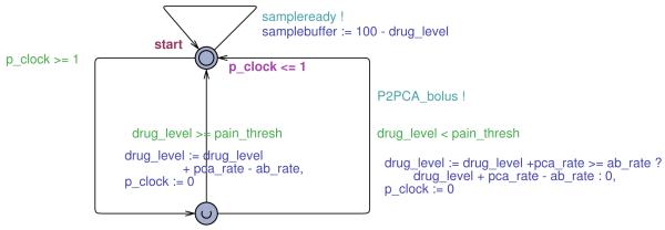
5) Patient Automaton
The Patient automaton, shown in Figure 12, periodically updates the drug level based on the flow rate of the pump and drug absorption rate. In addition, at any time, the model can deliver a sample as the function of the current drug level. The designed model implements a linear patient dynamics, which does not match the more realistic Simulink model. An important question that needs to be addressed is the consistency between the two models. Since the UPPAAL model of the controller uses significantly simplified patient dynamics, there is the possibility that verification results obtained on the UPPAAL model would not apply to the more detailed model and thus the system itself. Therefore, in the remaining of this subsection we address initialization of the Patient’s and PCA pump automatons.
Fig. 12.
Timed automaton for the patient.
6) Initializing model parameters
To determine values for the parameters of Patient and PCA pump automatons we consider the Patient’s behavior with respect to the safety requirements. From the safety analysis provided in the previous section for both designed controllers (i.e., both Supervisor designs), it can be reasoned that the focus of interest for the safety conditions is with the patient’s behavior in the Alarming region. In both of these cases it is required that the minimal time that the Patient can spend in the region is bounded by a value t̃crit (from (11)). Therefore, the value of t̃crit, the minimal time it takes for the patient to be overdosed, is an important consistency check for the models.
In the UPPAAL model, the value of tcrit may be different (we denote it ). This value can be obtained from the Patient model as:
| (13) |
where PCA_rateON = default_bolus_rate + default_rate and ⌈x⌉ denotes the smallest integer greater than or equal to x. To guarantee consistency between the UPPAAL and Simulink models, the value for has to be no greater than then the previously obtained value t̃crit. Therefore, from condition and (13), we can derive the condition for the UPPAAL model parameters (default_bolus_rate and default_rate from PCA automaton and ab_rate from the Patient automaton).
In our case, turns out to be 20 seconds for the initial values of the parameters that described patient dynamics and drug flow (pca_rate = 3, ab_rate = 2), which is an order of magnitude smaller than t̃crit. Clearly, the UPPAAL model overestimates the rate of change for the drug level in the patient body. And, since the system has been proven safe in this case, it would also be safe in a more realistic case. However, since we want to more realistically mimic the patient behavior in the Alarming region it is necessary to set the parameters in a way that:
| (14) |
This also allows relaxation of timing requirements imposed on other components in the control loop. For example, with this value it is possible to relax the value for the bound on network imposed delay (tnet) from Table I.
In addition, it is necessary to achieve consistency between UPPAAL and the physical patient model in cases when the pump is turned off. The goal is to minimize difference between the times (obtained from UPPAAL and Simulink models) that the patient would spend in the Alarming zone if the pump is turned off at the boundary of the Critical zone. Similarly as in the previous case, the condition that relates UPPAAL model parameters with the patient model from (1) can be obtained from (11) where ui = 0 (i.e., drug delivery is turned of):
| (15) |
where rate_down = ab_rate − default_bolus_rate. Finally, from (14), (15) the parameters for PCA and Patient automaton in the UPPAAL model can be obtained.
B. Verifying PCA System Safety Properties
The main safety property that needs to be verified on the UPPAAL model is whether or not the patient can enter the Critical region, where SpO2 and heart rate are low enough to indicate a respiratory arrest. Before verifying safety, however, we perform several auxiliary checks to ensure model sanity.
We express properties we verify in the subset of the Computational Tree Logic (CTL) [19] used by UPPAAL. The main temporal operators of this logic that we use are A□φ, which means that φ is satisfied in every state along every execution path from the current state, and A◇φ, meaning that φ is satisfied eventually along every path.
The first sanity check is the absence of deadlocks in the model. Another sanity check is that once the SpO2 level goes below the pain threshold, it eventually goes up. This property is captured by the temporal logic formula
| (16) |
Note that the property is defined in terms of the true SpO2 level as defined by the patient model, not the sensor reading obtained by the supervisor. Intuitively, this property should hold, because the normal infusion rate is lower than the drug absorption rate. Once the patient stops requesting new boluses and the last bolus infusion is over, the drug level will start decreasing and thus SpO2 and heart rate levels should increase, until they reach pain threshold again. Finally, we check that the pump is stopped if the patient ever enters the alarming region. Formally,
| (17) |
We consider this property to be a sanity check rather than a safety requirement, because wrong parameters of the model – for example, too short bolus duration or too high drug absorption rate – can make the system appear safe (that is, SpO2 level never goes too low), but it would be safe for the wrong reason. All sanity checks were passed by the UPPAAL model described above when no dropped messages are allowed. Clearly, property (17) does not hold if messages can be dropped.
Finally, we turn to checking the main safety property. With the threshold for the Critical region set to 70%, the property A□(samplebuffer ≤ critical) is satisfied if the stop message cannot be dropped. However, if losing messages is enabled in the network automaton, the property is not satisfied.
V. Failures and Fail-Safe PCA System
We have seen in Section IV that the system does not satisfy its safety property if network messages can be lost. Also, it can be observed from (4) that if any of the delays on the left side of the equation is significantly increased, the condition would not be satisfied. Increase in any of the delays can be caused by a component or network failures, which would result in an open-loop system.
To provide safety assurance realistic scenarios have to be taken into account, where network failures occur or PO accidentally gets detached from the Patient. Thus, the Supervisor’s control algorithm and PCA pump’s designs have to guarantee the system’s open-loop safety. For the case study this denotes that even if the Supervisor does not receive the right values for HR and/or SpO2 or the pump does not receive the command to disable the drug flow, the system design has to guarantee that the patient would not enter the Critical region. In addition, open-loop safety implies that even if the patient keeps pressing the button no drug flow will be enabled if there is a possibility that the amount of infused drug can harm the patient.
One way to design the system that complies with open-loop safety requirement is to make changes in the closed-loop system from Figure 2. In the modified system the pump receives activation command from the Supervisor (not the Patient) along with the duration of the drug flow (which does not have to be fixed). When the Patient presses the button if the Supervisor is informed about current HR and SpO2 values it is able to determine a duration of the pump’s activation (Δtsafe) that guarantees the patient’s safety. An additional condition is that the Supervisor will disregard the button press during tdel units of time after the pump is stopped. Here, tdel takes into account all the delays in the loop and is defined as follows:
The imposed condition ensures that the last drug delivery will take full effect before the next ‘button pressed’ command is sent to the Supervisor. In addition, it implies that the drug level function will reach its local maximum before HR and SpO2 measurements sent to the Supervisor are obtained. All constituents of tdel, except the network delay, can be calculated as described in the previous Section. We assume that if the message is delivered, the underlying real-time network provides a guaranteed bound on the network delay, as described in [7].
To calculate Δtsafe the following parameters are utilized:
hcur - last received SpO2 level,
Δh - worst case increase in SpO2 level due to system latencies while the pump is off,
Δh(h0, Δt) - maximal SpO2 decrease cause by drug flow of the duration Δt when the initial SpO2 level is h0.
Therefore, to satisfy the safety requirement, Δtsafe has to meet the condition:
| (18) |
It is worth noting that although we use SpO2 measurements to calculate Δtsafe, it is also possible to use HR measurements, as the boundaries of the Critical region (i.e., instead of ) correspond to same drug level values. The requirement, that after the pump is stopped, the Supervisor will disregard if the button is pressed for tdel time units, implies that when the button pressed command is accepted when Δh ≥ 0 (as SpO2 measurements decrease when drug level decreases), since the drug level will reach its local maximum before the measurements are taken. Therefore, the new safety condition can be obtained from:
| (19) |
To determine Δtsafe Theorem 1 can be utilized. In this case Eq. (19) is satisfied if:
| (20) |
Obviously if ( is the SpO2 threshold value for the Alarming region) Δtsafe would be greater than t̃crit. Similarly, if the patient is already in the Alarming region then Δtsafe ≤ t̃crit.
The system guarantees open-loop safety since, even if some (or all) of the messages are dropped, the patient would never enter the Critical region. The reason is that the pump activation command also contains the duration of the drug flow. In addition, if the flow durations are calculated properly, the pump will stop before safety requirement is breached.
To guarantee open-loop safety an assumption was made that the Supervisor is able to determine whether received measurements are valid. This is a reasonable assumption because modern POs send an invalid code in cases when valid measurements can not be obtained.3 Note that in this work we do not consider failures where component’s behavior differs from the behavior described by their models. For example, if the pump is active longer than requested, or if PO does not send an invalid code when it is unable to obtain valid measurements.
The presented solution is not the only way to guarantee open-loop safety. An alternative approach, which requires minimum change to existing PCA infusion pumps, is to have the Supervisor instruct the pump to pump the maximum amount of drugs that can be injected. Using a procedure similar to (20) the Supervisor can easily calculate the maximum allowed drug dosage. This system is also inherently fail-safe since the worst consequence of failed network, Supervisor, or PO is no drug injection, as in the previous case.
VI. Related Work
Formal methods have traditionally been used for verification of time-critical and safety-critical embedded systems [20]. However, until recently they have not been used for medical device certification. Formal techniques have been applied to improve medical device protocols [21] and safety [22]. In addition, in [10] the authors present the use of Extended Finite State Machines for model checking of the Computer Automated Resuscitation A medical device. Nonetheless, although these papers consider relevant clinical application, in all of them either a simplified patient model was utilized or the patient was not modeled at all.
Continuous monitoring of the blood oxygenation of patients receiving PCA infusions has been done in the past and even commercially implemented. The Alaris 8210 SpO2 Module connects to the Alaris 8000 pump controller and adds the ability to pause infusions based on a target SpO2. Our approach shows how a similar system could be designed and validated. In particular, while the available commercial system is provided as a tightly-integrated system from a single vendor, our approach could be used to design and validate systems based on devices from multiple sources as long as the timing and other necessary information is available.
VII. Conclusion
We have presented a clinically relevant case study of the closed-loop control of a PCA infusion pump. To be able to perform safety analysis of the closed-loop medical system we have used a model-driven approach that combines simulation-based validation of a continuous-time system model in Simulink with formal verification of a more abstract model using timed automata and the UPPAAL tool. In this case, the key to keeping the two models consistent is to derive timing parameters of the system from the Simulink model and use these constants in the UPPAAL model.
For the case study, we have shown that the system is safe under no failure assumptions. We identify how to deal with some of the failures that manifest as unbounded delays. The proposed method is based on the well-known notion of timed lease used in fault-tolerant distributed systems. We believe that such a technique can be applied to other tightly integrated medical systems in which fail safe is essential.
The dynamics in the considered case study is relatively simple. This choice is made on purpose, to better present the steps in our approach, including the analysis of a system with uncertain parameters. Given the simple case study, we believe that our approach allows us to construct safety cases for regulatory approval of closed-loop medical systems. With more complicated dynamics, some of the steps become more difficult; in particular, the derivation of timing parameters for patient model with uncertain parameters may require more sophisticated methods and further research may be required.
In this paper, we highlight the need for model-driven safety analysis of the closed-loop medical systems and, on a specific case study, we emphasize potential problems that might occur. However, it it will be of interest to extend our approach to more general closed-loop medical scenarios.
Acknowledgments
Research is supported in part by the National Science Foundation grants CNS-0834524 and CNS-0930647. POC: Insup Lee, lee@cis.upenn.edu
Appendix A
Proof of Theorem 1
Proof: Consider the LTI system from (7). The time response at time t0 + t for all t ≥ 0 can be computed as ([23]):
Therefore, if u(t) = ui for all t ≥ t0, where ui is a constant vector, the system evolution can be described as:
| (21) |
where In ∈ ℝn×n identity matrix. Due to the fact that for matrices P, P1 and Q of the appropriate dimensions ||PQ|| ≤ ||P|| · ||Q|| and ||P + Q|| ≤ ||P|| + ||Q||, from (21) it is possible to provide the following bound:
| (22) |
Now, consider the term ||eAt − In||. From the definition of the exponential function we can obtain:
| (23) |
Similarly it can be shown:
| (24) |
From (22)-(24) it is possible to obtain a bound on the change in the system’s output:
Therefore, from the previous equation:
| (25) |
for all matrices A, B and C that belong to the polyhedrons ℜ{A}, ℜ{B} and ℜ{C} respectively.
Eq. (25) provides a lower bound on the value t for which the system output can progress from point y(t0) to the point y(t0+ t) for any values of the aforementioned matrices. The bound is a function of the patient parameters (i.e., matrices A, B and C). The goal is to provide the bound value that is the minimum of the term on the right side of (25) for all matrices A, B and C belonging to the corresponding polyhedrons.
The term on the right side of (25) decreases as the values ||A||, ||C||, {{x0||, ||A||−1 and ||Bui|| increase. Note that it is not possible to calculate the value for ||A|| that will minimize the term. Thus, for simplicity two independent problems are considered:
As , by defining Ã, B̃, C̃ as in the Theorem statement, Eq. (8) can be obtained.
Appendix B
Proof of Theorem 2
Proof: Assume that there exist a matrix à = argmaxA∈ℜ{A} ||A||, such that à is not a vertex and that there does not exist a matrix A ∈ ℜ{A} such that ||A|| = ||Ã||. Since à is not a vertex and polyhedron ℜ{A} is bounded there exists a matrix element ãij such that
| (26) |
Denote with ÂL and ÂH matrices whose all elements are equal to the appropriate elements from à except the element from ith row and jth column, and lets assume that these elements are and , where ε > 0 is chosen such that (from (26) such ε exists). Since à is the unique minimization argument for the optimization problem then ||Ã|| > ||ÂL|| and ||Ã|| > ||ÂH||. Therefore:
| (27) |
On the other hand since ||A|| is a convex function and from the fact that à = ½(ÂL + ÂH) it can be concluded:
which is in contradiction with (27). Thus, for the optimization problem there does not exist the unique minimization argument that is not a vertex, implying that there exist an optimal solution Amax that is a vertex of polyhedron ℜ{A}.
Footnotes
Although we can not guarantee that the uncertainty bound (i.e., 10%) can be used to model all types of uncertainties in the Patient model, we have opted to use it as it provides a way to model different types of patients. However, if Patient’s dynamics (i.e., pharmacokinetics) is better understood for particular types of patient populations, a new uncertainty bound can be easily adopted.
Note that matrix A does not have to be a square matrix.
Detachment of the probes from the patient’s body or movements of the patient’s hand are main reasons why POs do not obtain valid values.
The paper is submitted to the Special Section on Cyber-Physical Systems and Cooperating-Objects: The New Frontier for Embedded Systems. The initial version of this paper was presented in [1].
Contributor Information
Miroslav Pajic, Department of Electrical & System Engineering, University of Pennsylvania, Philadelphia, PA 19104, USA USA, pajic@seas.upenn.edu.
Rahul Mangharam, Department of Electrical & System Engineering, University of Pennsylvania, Philadelphia, PA 19104, USA USA, rahulm@seas.upenn.edu.
Oleg Sokolsky, Department Computer & Information Science, University of Pennsylvania, Philadelphia, PA 19104, USA USA, sokolsky@seas.upenn.edu.
David Arney, Department Computer & Information Science, University of Pennsylvania, Philadelphia, PA 19104, USA USA, arney@seas.upenn.edu.
Julian Goldman, Mass. General Hospital & CIMIT, Boston, MA 19104, USA USA, jmgoldman@partners.org.
Insup Lee, Department Computer & Information Science, University of Pennsylvania, Philadelphia, PA 19104, USA USA, lee@seas.upenn.edu.
REFERENCES
- [1].Arney D, Pajic M, Goldman JM, Lee I, Mangharam R, Sokolsky O. Toward patient safety in closed-loop medical device systems; ICCPS ’10: Proceedings of the 1st ACM/IEEE International Conference on Cyber-Physical Systems; 2010.pp. 139–148. [Google Scholar]
- [2].STAM F2761-2009. Medical Devices and Medical Systems — Essential Safety Requirements for Equipment Comprising the Patient-Centric Integrated Clinical Environment (ICE), Part 1: General Requirements and Conceptual Model. ASTM International; 2009. [Google Scholar]
- [3].Goldman J, Schrenker R, Jackson J, Whitehead S. Plug-and-play in the operating room of the future. Biomedical Instrumentation and Technology. 2005;39(3):194–199. doi: 10.2345/0899-8205(2005)39[194:PITORO]2.0.CO;2. [DOI] [PubMed] [Google Scholar]
- [4].Alur R, Dill D. A theory of timed automata. Theoretical Computer Science. 1994;126(2):183–235. [Google Scholar]
- [5].Behrmann G, David A, Larsen K. A tutorial on uppaal. Formal Methods for the Design of Real-Time Systems (revised lectures) 2004;3185:200–237. ser. LNCS. [Google Scholar]
- [6].Lee I, Pappas GJ, Cleaveland R, Hatcliff J, Krogh BH, Lee P, Rubin H, Sha L. High-Confidence Medical Device Software and Systems. IEEE Computer. 2006;39(4):139–148. [Google Scholar]
- [7].Fischmeister S, Goldman JM, Lee I, Trausmuth R. Plug-and-play for medical devices: Experiences from a case study. Biomedical Instrumentation & Technology. 2009;43(4):313–317. doi: 10.2345/0899-8205-43.4.313. [DOI] [PubMed] [Google Scholar]
- [8].Infusion pump improvement initiative. Center for Devices and Radiological Health, U.S. Food and Drug Administration; Apr, 2010. White Paper. [Google Scholar]
- [9].Nuckols TK, Bower AG, Paddock SM, Hilborne LH, Wallace P, Rothschild JM, Griffin A, Fairbanks RJ, Carlson B, Panzer RJ, Brook RH. Programmable infusion pumps in ICUs: An analysis of corresponding adverse drug events. Journal of General Internal Medicine. 2008 Jan;23(Supplement 1):41–45. doi: 10.1007/s11606-007-0414-y. [DOI] [PMC free article] [PubMed] [Google Scholar]
- [10].Arney D, Jetley R, Jones P, Lee I, Sokolsky O. Formal methods based development of a PCA infusion pump reference model: Generic Infusion Pump (GIP) project; HCMDSS-MDPNP’07: Proc. of Joint Workshop on High Confidence Medical Devices, Software, and Systems and Medical Device Plug-and-Play Interoperability; 2007.pp. 23–33. [Google Scholar]
- [11].Chan V, Underwood S. Texas Instruments. Nov, 2005. A single-chip pulsoximeter design using the MSP430. Tech. Rep. SLAA274. [Google Scholar]
- [12].Bequette BW, editor. Process control: modeling, design, and simulation. 2nd ed. Prentice Hall; 2003. [Google Scholar]
- [13].Jevon P, Ewens B, editors. Monitoring the Critically Ill Patient. 2nd ed. Wiley-Blackwell; 2007. [Google Scholar]
- [14].Mazoit JX, Butscher K, Samii K. Morphine in postoperative patients: Pharmacokinetics and pharmacodynamics of metabolites. Anesthesia and Analgesia. 2007;105(1):70–78. doi: 10.1213/01.ane.0000265557.73688.32. [DOI] [PubMed] [Google Scholar]
- [15].Grant M, Boyd S. CVX: Matlab software for disciplined convex programming. 2009 Jun; http://stanford.edu/boyd/cvx.
- [16].Yedavalli RK, Ashokkumar CR. Time response bounds for linear parametric uncertain systems. International Journal of Systems Science. 2000;31(2):177–188. [Google Scholar]
- [17].Alur R, Kanade A, Ramesh S, Shashidhar KC. Symbolic analysis for improving simulation coverage of simulink/stateflow models; EMSOFT ’08: Proceedings of the 8th ACM international conference on Embedded software; 2008.pp. 89–98. [Google Scholar]
- [18].Ackermann C, Ray A, Cleaveland R, Heit J, Martin C, Shelton C. Model based design verification - a monitor based approach; Society of Automotive Engineers, World Congress; 2008. [Google Scholar]
- [19].Clarke EM, Emerson EA. Design and synthesis of synchronization skeletons using branching time temporal logic; Workshop on Logic of Programs; 1981. pp. 52–71. ser. LNCS. [Google Scholar]
- [20].Clarke EM, Wing JM. Formal Methods: State of the Art and Future Directions. ACM Comput. Surv. 1996;28(4) [Google Scholar]
- [21].Alur R, Arney D, Gunter EL, Lee I, Lee J, Nam W, Pearce F, Albert SV, Zhou J. Formal specifications and analysis of the computer-assisted resuscitation algorithm (CARA) Infusion Pump Control System. Intl. J. Software Tools for Technology Transfer. 2004;5(4):308–319. [Google Scholar]
- [22].ten Teije A, Marcos M, Balser M, van Croonenborg J, Duelli C, van Harmelen F, Lucas P, Miksch S, Reif W, Rosenbrand K, Seyfang A. Improving Medical Protocols by Formal Methods. Artif. Intell. Med. 2006;36(3):193–209. doi: 10.1016/j.artmed.2005.10.006. [DOI] [PubMed] [Google Scholar]
- [23].Rugh WJ. Linear system theory. 2nd ed. Prentice-Hall, Inc.; 1996. [Google Scholar]