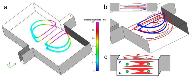
Fig. 3.

Numerical models suggest four orbits (two z-planes) for particle trapping. (a) The planar orbits symmetrically located in two chambers. The velocity closer to the main channel is higher, with the lowest velocity at the back of the vortex orbit. Flow is from left to right at Re=154. (b) Perspective view and sideview (inset) of the 3-D vortex structure. The trapping orbits (blue) are located at ¼H and ¾H, vertically centered at each of the two vortices (red). (c) The schematic illustration of particle trapping within the vortices.
