Fig. 5.
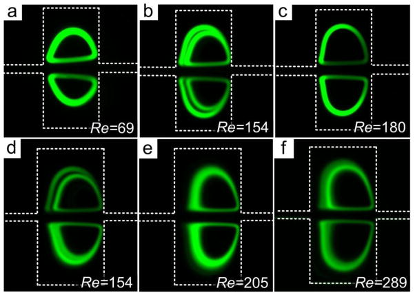
Evolution of particle orbits corresponding to input Re. (a) Single small orbits at low Re in a 300 μm × 300 μm chamber. (b) Double orbits at intermediate Re. (c) Particles trapped in the large orbit at high Re. The inner particle trajectory is not present in this image. (d) Double orbits in large 400 μm × 400 μm chamber. (e) At higher Re, particles fill in the gap between the double orbits. (f) Distortion of orbits and loss of particles at excessive high Re. In all experiments, 20 μm diameter particles were used; trapping chambers were 300 μm × 300 μm in panels (a)–(c) and 400 μm × 400 μm in panels (d)–(f); microchannel height was 100 μm in all experiments.

