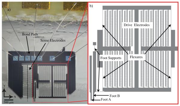
Figure 1.
Photograph and enlarged model of actuator for shear characterization. (a) The ASC is driven electrostatically by voltage applied to the device through bond pads and wire bonds. (b) Enlarged model of the drive electrodes, which are supported by four flexures and separated from the remainder of the device. These flexures are representative of springs in parallel with a total stiffness represented as kspring. The actuator foot is connected to a base, and to the drive electrodes via the two-foot supports as shown. The operation principle of ASC relies on electrostatic force generation where the drive electrodes move Foot B to the left. In this depiction Foot A is removed from the remainder of the device and appears to be floating; however, it is always stationary.

