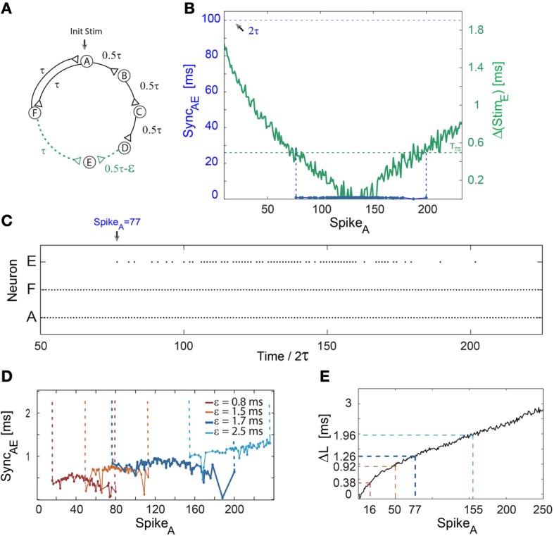
Figure 3.

Short epochs of synchrony not accompanied by a change in frequency. Notations used: SyncAE, the absolute time-lag between the spikes of neurons A and E; Δ(StimE), the absolute time difference between two weak stimulations to neuron E; ΔL, defined as ΔLB + ΔLC + ΔLD − ΔLF. (A) Schematic of a neuronal circuit consisting of six neurons and weak/strong stimulations represented by dashed (green)/full (black) lines. (B) Experimental measurements of Δ(StimE), similar to Δ(StimC) in Figure 1B, with ε ≈ 1.7 ms, τ = 50 ms and TTS ≈ 0.5 ms (presented by the dashed horizontal green line). The time delay between neurons A and E, ~2τ, is denoted by the dashed horizontal black line. The firing region of neuron E (blue dots bounded by dashed vertical guidelines), which is at nearly zero-lag synchronization with the firing of neuron A, SyncAE ≈ 0, starts after 77 spikes of neuron A. The temporary firing of E terminates after ~200 spikes of neuron A. (C) Spike trains of neurons A, F, and E, indicating a steady firing frequency (~10 Hz) of the neuronal circuit independent of the firing of neuron E, where an epoch of synchrony, SyncAE ≈ 0, begins at time/2τ = 77 (at spike 77 of neuron A). (D) The number of spikes prior to the firing of neuron E increases with ε. The mild increase in the firing mismatch, SyncAE, is attributed to the additional increase by ε of the initial 2τ delay loop (E fires ~2τ + ε laggard to A, however, the time-gap between consecutive firings of A is ~2τ + 2ε). The data for ε = 1.7 (blue) is the same as in (B,C). (E) ΔL for repeated stimulations at 10 Hz. ΔL at the synchrony leap for different ε are colored following (D). The number of spikes per neuron (e.g., SpikeA), n, until the leap to synchrony increases with ε and can be obtained from Equation (1), where ΔLD is substituted by ΔL.
