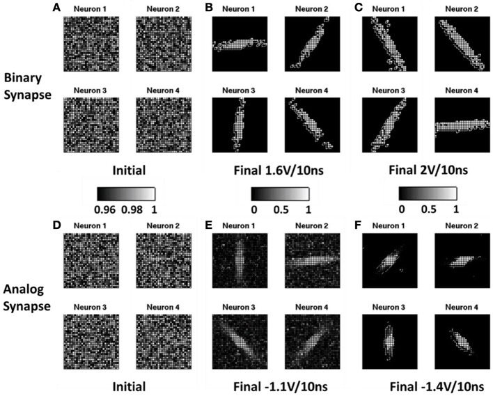
Figure 5.
Simulated normalized conductance map between the input layer neurons and the output layer neurons utilizing binary synapse with stochastic learning (A–C) and analog synapse with depression-only learning (D–F). The normalization is done with respect to a reference that is the highest conductance in the synapse array before the training. Initially, the resistances of all the oxide synaptic devices were randomized with a distribution centered at on-state for binary synapse (A) and for analog synapse (D). After the training, the resistances diverge. With appropriate programming condition, the 4 distinct orientations emerge, e.g., for binary synapse using +1.6 V/10 ns SET pulse (B) and for analog synapse using −1.1 V/10 ns RESET pulse (E). If the programming condition not optimized, only 3 distinct orientations emerge, e.g., for binary synapse using +2 V/10 ns SET pulse (C) and for analog synapse using −1.4 V/10 ns RESET pulse (F).

