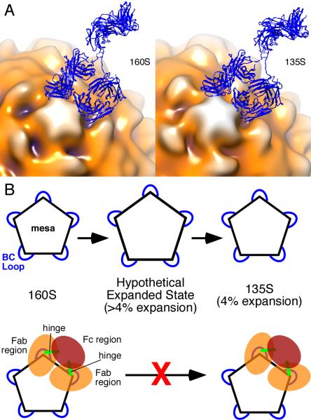
FIGURE 4.
Model for inhibition of 160S-to-135S transition by C3 antibody. (A) Models of C3 Ab (blue ribbon) bound to 160S (left) and 135S (right) particles. Fitted coordinates for Fab (from (12)) were placed in adjacent epitopes, and their non-antigen-binding (constant) domains were rotated towards each other about their respective elbow angles to allow the two Fabs to be joined to coordinates from the Fc portion of an IgG crystal structure (47). The antigen-binding (variable) domains were not moved. The IgG model was made with the use of UCSF Chimera (24). The 160S (17) and 135S (13) structures are from previously published studies and are shown as surface renderings in multiple colors. Darker hues show portions of poliovirus capsid that are closer to the particle center. According to our modeling, an IgG must bind to two adjacent BC loops. A single IgG molecule cannot bind two loops that are farther apart. Pictures are from the same view direction. (See also Video 4.) (B) Expansion model of poliovirus. Pentagon represents the mesa on the poliovirus capsid with blue loops corresponding to the BC loop. Top row, the 160S-to-135S transition has a hypothesized transient intermediate state in which the BC loops are separated by a relatively larger distance compared to the final 4% expansion observed in the 135S particle. Bottom row, according to the model presented on the top row, binding of the C3 antibody prevents the transition from 160S to 135S particle because the antibody prevents expansion beyond 4%. Note that C3 antibody can bind to preformed 135S particles (bottom row, right) (11). 160S particles bound to C3 Fabs would still be able to make the 160S-to-135S conversion because the Fab regions are not linked.

