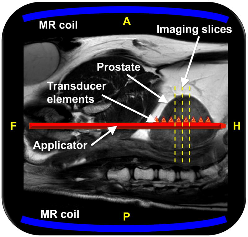
Figure 1.

Schematic of the MRI-guided US therapy setup. The sagittal imaging plane is shown, with the dog supine on the MRI table top, and the US applicator shown in red is advanced along the urethra to the level of the prostate. The central three axial imaging slice positions for the thermometry sequence are shown with yellow dashed lines, and the two MRI coils are depicted in blue. Depiction of the applicator and its eight transducer elements as triangles within the prostate are meant to be illustrative. A, P, F, and H denote anterior, posterior, feet, and head, respectively.
