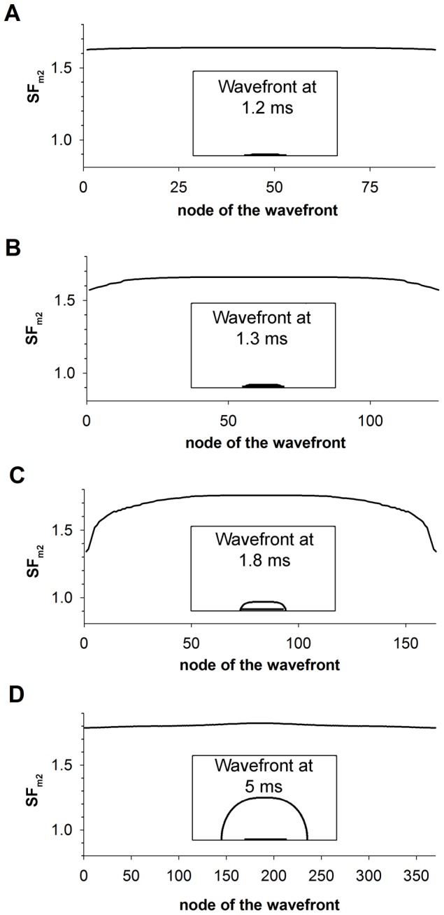
Figure 4. SFm2 along the wavefront.

SFm2 along the symmetrical half of the wavefront propagating in the up direction in the control tissue stimulated with a 3 mm×0.1 mm electrode placed in the centre of the tissue at four instants, 1.2 ms (A), 1.3 ms (B), 1.5 (C) and 5 ms (D) after the onset on the simulation. Insets highlight the wavefront and the electrode in half of the tissue at the corresponding instants.
