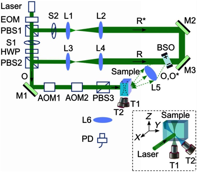
Fig. 1.
Schematic of the experimental setup. AOM, acousto-optic modulator; BSO, ; EOM, electro-optic modulator; HWP, half-wave plate; L, lens; M, mirror; , signal light; , time-reversed signal light; PBS, polarizing beam splitter; PD, photodiode; , reference beam; , conjugated reference beam; S, shutter; T, ultrasound transducer. Coordinates: , and of T1. The pressure at the ultrasound focus was 1.0 MPa peak-to-peak. To enhance the phase conjugation efficiency, a 2.1-kHz, square waveform external electric field was applied across the BSO.

