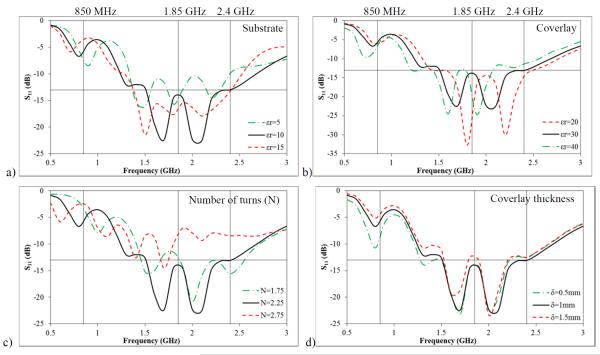
Figure 3.
Parametric simulations to improve impedance matching at the interface between antenna and load. a) S11 vs. substrate relative permittivity; b) S11 vs. coverlay relative permittivity; c) S11 vs. number of log-spiral turns and d) S11 vs. coverlay thickness. Nominal values: N = 2.25, δcoverlay = 1 mm, εr,coverlay = 30 and εr,substrate = 10.2.

