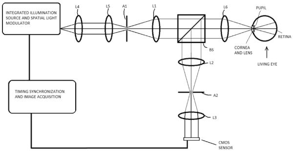
Figure 3.

Optical design schematic of a confocal imaging system using a DLP source and rolling shutter CMOS detector adapted for retinal imaging. Apertures A1 and A2 are located at conjugate pupil planes and are used to separate the illumination and imaging pathways to remove corneal reflections. Lenses L1–L6 direct the illumination and imaging light through the system. Pellicle beamsplitter BS directs a portion of imaging light from the retina to the CMOS sensor.
