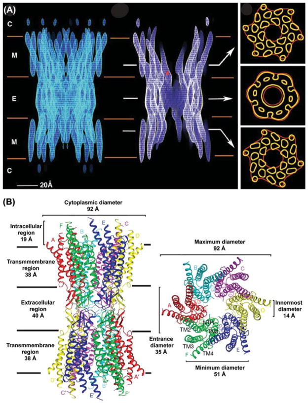
Figure 2.
Structure of a gap junction channel. (A) Cryo-EM images of a Cx43 channel truncated at T263. The left panel is a full side view of the channel. In the middle image, electron density has been cropped to reveal channel interior. The cytoplasmic (C), membrane (M), and extracellular (E) boundaries are indicated. The asterisk (*) is located at the narrowest point within the intercellular channel. Arrows indicate the area from which the cross sections shown on the right were taken. Tubular densities in the top and bottom sections of the right panel are from the 24 α-helical transmembrane domains. The density in the middle section is from the six connexins that comprise a hexameric connexon. Image is reprinted with permission from (Unger et al., 1999). (B) Ribbon diagram of the Cx26 gap junction channel X-ray crystal structure. The channel dimensions are provided in the side view (left) and top view (right) of the channel. The transmembrane domains (TM1–4) and connexins (A–F) are indicated. Image is reprinted with permission (Maeda et al., 2009).

