Abstract
A novel robotic sensor is proposed to measure both the contact angle and the force acting between the tip of a surgical robot and soft tissue. The sensor is manufactured using a planar lithography process that generates microchannels that are subsequently filled with a conductive liquid. The planar geometry is then molded onto a hemispherical plastic scaffolding in a geometric configuration enabling estimation of the contact angle (angle between robot tip tangent and tissue surface normal) by the rotation of the sensor around its roll axis. Contact force can also be estimated by monitoring the changes in resistance in each microchannel. Bench top experimental results indicate that, on average, the sensor can estimate the angle of contact to within ±2° and the contact force to within ±5.3 g.
I. INTRODUCTION
The use of robotic technology in medical practice holds the potential for creating new minimally invasive procedures as well as improving the outcomes of existing procedures. One potential disadvantage of moving from handheld tools (including laparoscopic tools) to teleoperated robots is the loss of touch sensing on the clinician’s fingers. Since the interventionalist is unable to feel the interaction between the robot and the tissue, they must rely instead on imaging. Tissue deformation must be used to infer contact and to assess the magnitude of the applied force. In situations where high fidelity stereoscopic endoscopy can be utilized, this form of sensory substitution can be highly effective.
There are many instances, however, when image-based tissue interaction imposes limitations on the precision and safety of tissue interactions. In these situations, direct sensing of robot-tissue interaction and the capability to provide the clinician with information regarding the contact orientation and forces applied to tissue would greatly facilitate complex repairs. Furthermore, such sensing could also enable automatic compensation for physiologic motion to maintain a desired tissue contact state.
One specific example where such sensing would be useful is in intracardiac beating-heart surgery. Since the beating heart is filled with blood, endoscopy is not an option and the standard imaging modalities are 3D ultrasound and fluoroscopy. Both modalities impose limitations. Ultrasound images are noisy and, in addition, metal instruments produce imaging artifacts that obscure both the precise location of the instrument as well as nearby tissue [1]. Fluoroscopy, in contrast, provides detailed images of instruments, but does not provide images of the tissue.
While our prior results have shown that robotics can enable structural repairs to be performed within the beating heart [2], this work has also demonstrated the difficulty of relying entirely on imaging to accurately assess (1) the existence of tissue contact, (2) the orientation of tissue contact and (3) the contact force. This is illustrated in the ultrasound image of Figure 1 showing a concentric tube robot positioned inside a beating porcine heart with its tip approaching the atrial septum. Owing to artifacts and resolution limits, the robot can appear to be in contact even when it is ~5 mm away from the tissue. Furthermore, while specific values of contact angles, e.g., Φ ≤ 50°, and contact forces, F ≈ 50 grams, may be needed to properly deploy a tool into the tissue, these quantities can be very difficult to estimate visually.
Fig. 1.
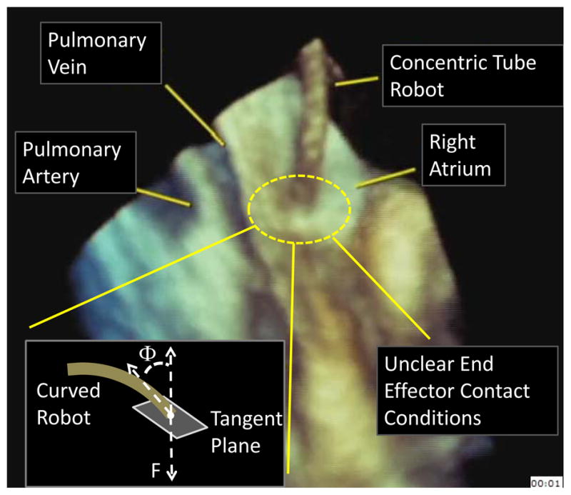
Estimating tissue contact state using 3D echocardiography inside a beating porcine heart.
The contribution of this paper is to propose a mm-scale soft robot tip sensor that can be used to measure both contact orientation angle, Φ, as well as contact force, F. Prior work has considered force estimation, but not contact angle estimation. For example, several other groups have sought to sense force at the tip of a catheter or surgical robot. Kessner et al. proposed a 3D printed uniaxial force sensor that uses reflectance along an optical fiber to detect axial force [3], [4]. Ataollahi et al. used a similar technique, yet paid close attention to the materials in order to maintain MRI compatibility [5]. In an alternate approach, Tung et al. used a laser-machined array of Nitinol strain gages to sense the tip position of an interventional catheter [6].
As an alternative to optical and strain gage technologies, we propose a soft robotic sensor using conductive microstructures, as inspired by [7] and [8], to enable simultaneous measurement of tip force and orientation.
The paper is arranged as follows. Sensor requirements, conductive microchannel shape, design and manufacturing are described in Section II. Experimental characterization and sensitivity analysis of the hemispherical tip sensor are presented in Section III. The sensor is experimentally validated with a set of sample data in Section IV.
II. Sensor Development
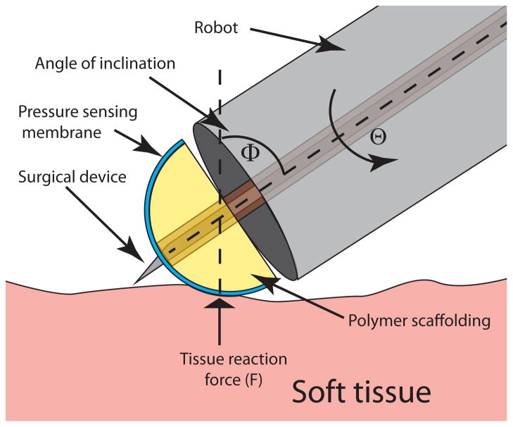
To provide sufficient information for guiding tissue interaction, the sensor is intended to measure tip contact force, F, as well as orientation angle, Φ, as defined in Fig. 1. A motivating scenario is illustrated in Fig. 2 which shows a stylet extended through the sensor. This maneuver, corresponding to a step in the cardiac procedure described in [2], is intended to pierce the tissue in a specific location. If the contact angle Φ is not maintained at Φ ≤~ 50°, the stylet will not puncture the tissue, but instead will slide along its surface causing tissue damage and potentially creating a puncture in an inappropriate location. Furthermore, if the contact force, F, is too small, the stylet will push the tissue out of contact with the robot without puncturing it. If F is too large, the robot itself may tear a large hole in the tissue.
Fig. 2.
Schematic of an application scenario of a miniature tip force sensor. Contact force, F, roll angle, Θ, and contact angle, Φ, are labeled.
Consideration of tasks similar to this example leads to the following set of assumptions and design specifications.
-
Assumption 1
It is assumed that the robot can control the roll angle of the sensor. For example, using a concentric tube robot or other type of continuum robot, the sensor could be attached to an inner tube passing through the robot lumen and actuated at its base.
-
Specification 1
The desired force range is 0–100 g.
-
Specification 2
The device is required to be able to sense tissue reaction loads at any contact angle in the range of Φ ∈ [0°, 90°].
-
Specification 3
Force calibration should, preferably, be independent of contact angle, Φ.
-
Specification 4
Sensing should be distributed around the roll axis of the sensor to minimize sensing dead zones.
-
Specification 5
The sensor itself should possess a lumen so that surgical tools can be passed through it such that their interaction with tissue can be controlled using sensor outputs. Note that this specification may conflict with Specification 2 since it prevents sensing within the area of the lumen. In this case, Specification 2 may be replaced with Φ ∈ [Φmin, 90°]. (This specification was deferred for future work.)
-
Specification 6
Sensor diameter should be 5 mm or less. In combination, these design requirements yield a device shaped in the form of a hemispherical tip mounted at the end of a cannula. Given this overall shape, soft sensing technologies are chosen to measure the loading and contact configuration of the hemispherical tip, owing to the similarity of their elastic properties with those of actual tissue, their adaptability to various geometries through deformation, and the availability of a variety of manufacturing techniques.
In particular, the soft sensors are based on elastic deformation of microfluidic channels embedded in Polydimethyl-siloxane (PDMS) and filled with conductive liquid metal eutectic Gallium-Indium (eGaIn) [9], [10]. Given that the electrical resistance of a liquid metal filled channel is inversely proportional to its cross sectional area, physical deformation due to an external load on the channels can be correlated with a resistance change, thus providing means to measure the load in question.
A. Design of Microchannel Geometry
To achieve the desired force sensitivity, the design technique of [8] is employed which uses stress raisers on the sensing channels via contact with a harder material. Thus, the hemispherical tip itself is manufactured from urethane plastic, and used as scaffolding for a thin layer of PDMS (≈300 μm thick) with embedded sensing microchannels.
To achieve uniform sensitivity to force with respect to both roll angle and contact angle, Φ, the hemispherical surface could feature a two dimensional array of discrete pressure sensors, thus forming a sensing grid. With this approach, sensor outputs could include both contact angles (roll angle Θ and contact angle Φ) as well as contact force, F. Practical manufacturing limitations, however, that include placing enough micro-wires to address each sensor individually on the limited surface area of the hemisphere render the sensor array approach very challenging technologically.
Instead, the approach taken here is to view sensor roll angle Θ as a robot-controllable input degree of freedom with Φ and F as sensor outputs. This approach enables the use of exploratory sensor rolling motions through predefined angular amplitudes to obtain estimates of Φ and F. Note that the contact motion associated with variations in Θ corresponds to the sensor spinning in place on the tissue, which is typically slippery.
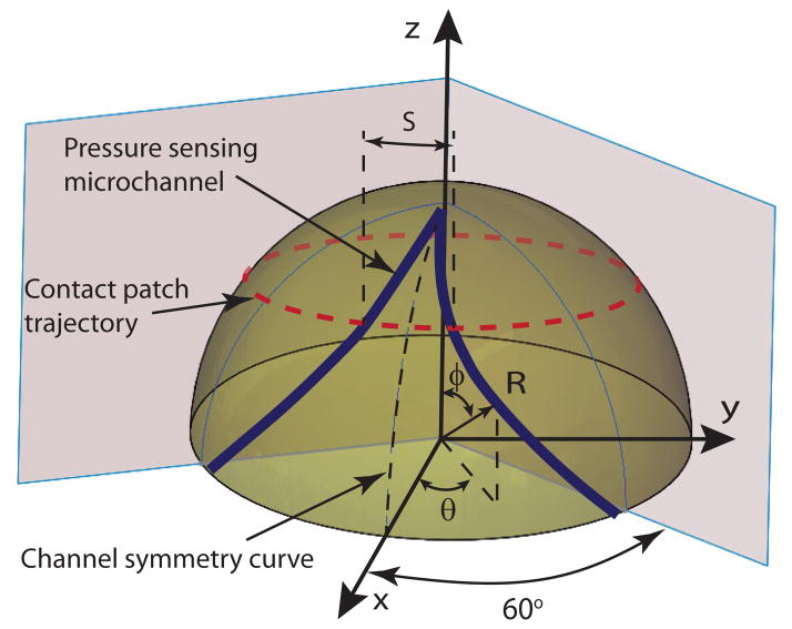
The resulting design template, as shown in Fig. 3, is characterized by a set of sensing micro channels that start and end at the base of the hemispherical cap with their midpoint approaching the top of the hemisphere. The channel pattern is repeated around the perimeter of the hemisphere n times to create n independent sensors. As the sensor is rotated around its roll axis, the center of its contact patch describes a circular trajectory, as illustrated in the figure. In one complete rotation, each sensing channel will be compressed under the contact patch twice and the spatial separation between the compression peaks can be correlated in terms of arc length S, and, thus, change in roll angle ΔΘ.
Fig. 3.
Sensor channel layout on a hemispherical sensing tip.
This spatial separation, together with adequate sensor channel geometry, can be employed to estimate contact angle, Φ. To provide a uniform sensitivity to contact angle, the curves, shown in Fig. 3, that describe the sensor channels can be selected such that the arc length S between the two channels of each sensor varies linearly with contact angle, Φ. This concept serves as the basis for the development of the sensor as described below.
Given manufacturing constraints, three discrete sensing channels (n = 3) are employed on the hemispherical surface with each sensor spanning 120° and, due to symmetry of the channel over the channel symmetry curve of Fig. 3, each half-channel spans 60°. Furthermore, since S ∝ θ, and Φ= φ, where θ and φ are variables of a spherical coordinate set, the linearity relationship requirement results in , where a is a constant. Imposing boundary constraints of θ = 60° when φ = 90°, the relationship between the roll and contact angles yielding linearity between S and Φ is
| (1) |
While these calculations neglect the existence of a central tool lumen, the results can be modified easily to accommodate one.
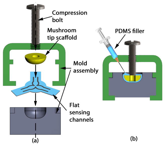
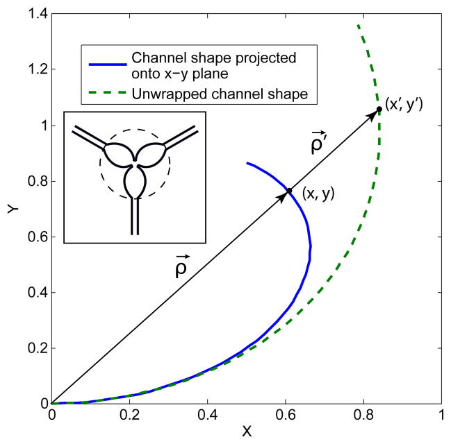
Specification 6, limiting the sensor diameter to 5 mm or less, restricts manufacturing techniques to those based on planar lithography. Adaptation of the resultant planar channels onto a spherical scaffold is achieved by wrapping and molding techniques, as illustrated in the molding assembly schematic of Fig. 4. The inverse of this problem is to effectively unwrap the channel curves from a spherical surface onto a plane, guided by the molding constraint that no stretching of the channels in the radial direction is allowed, i.e. in the ρ⃗ direction of Fig. 5.
Fig. 4.
Molding flat array of sensing channels onto a hemispherical tip scaffold. (a) Section view of the mold assembly, (b) Assembled mold with hemispherical tip.
Fig. 5.
Schematic of sensing channel unwrapping from spherical onto planar geometry. Inset portrays actual lithography mask used to pattern the three sensing channels of the planar array. Each sensor arm in the lithography mask is the same shape as the unwrapped channel shape illustrated in the main figure.
To obtain the parameteric equation of the sensing channels to be wrapped onto a sphere, the 3D shape of the channel inscribed on the surface of the spherical tip is projected onto the x-y plane and then nonlinearly warped in the radial direction, thus preventing any stretching as the channels are wrapped around the sphere. Given the previously established linear relationship of (1), the parametric equation of the projection of a half channel inscribed on a hemisphere of unit radius (R = 1) onto the x-y plane is given by
| (2) |
| (3) |
and the radial distance of any point (x, y) on the projected curve and the origin is
| (4) |
The amount each point (x, y) is radially stretched is defined by the difference between the arc length to a point on the surface of a sphere and its projection length. Since the arc length to the point (x, y) on the spherical surface is L = arcsin(|ρ⃗|), the projected channel curve needs to be radially stretched by the amount γ ≡ L − |ρ⃗| = φ − sin φ, after substitution of Eq. (4). Thus each point on the existing curve maps onto the unwrapped channel curve via the affine transformation:
| (5) |
where ρ⃗′ determines the position of a point {x′, y′}. Substituting for all the known quantities, we obtain the following parametrization of the unwrapped sensing channel curve as a function of φ:
| (6) |
This equation, after linear scaling to fit a particular sensor tip radius, is employed to yield planar channel geometries that can be wrapped without radial stretching onto a spherical tip. The full unwrapped array containing three sensors used as a lithographic mask is portrayed in the inset of Fig. 5.
B. Hemispherical Tip Sensor Manufacturing
The manufacturing steps to create planar microchannel sensors closely mimic the recipe provided by Kramer et al. [11]. In particular, empty channels are patterned in a 300 μm substrate of PDMS through a photolithography process, as illustrated in Fig. 6(a). The channels are later filled through their corresponding ports with eGaIn, and sealed with uncured PDMS, resulting in flat sheets with three embedded sensors portrayed in Fig. 6(b). The sensing channels are 80 μm tall and 250 μm wide. These flat sheets are forced into the cavity of a plastic mold, thus wrapping around the hemispherical tip, and compressed with a bolt (Fig. 4(a)). Uncured PDMS is injected into the cavity creating a uniform, smooth outer layer and encapsulating the hemispherical plastic scaffolding. Finally, the entire mold is degassed and cured at 80°C, and the sensor is mounted onto a 1.44 mm OD polyimide tube (Microlumen Inc., Oldsmar, FL) for characterization purposes (Fig. 6(c)). The resultant sensor is ≈4.8 mm in diameter and ≈1.7 mm in height. Note that the current prototype does not feature a central lumen for tool delivery due to increased manufacturing complexity, leaving this feature for a future sensor implementation.
Fig. 6.

Soft sensor manufacturing. (a) Flat channel geometry with fill ports. (b) Sensing channels filled with eGaIn. Cutting on dotted lines minimized sensor stretching during molding. (c) Completed sensor with channel-embedded PDMS sheet molded to plastic hemispherical tip and mounted on indentation cannula. Inset provides close-up view.
III. Sensor Characterization
A. Experimental Apparatus
Figure 7 shows the mechanical aspects of the characterization apparatus. A Newport rotary stage is mounted to a Newport linear stage for manual control of Φ and z-axis displacement, respectively. A Faulhaber Model 3257V0040 brushed DC motor coupled with a HEDS 5500 optical encoder in quadrature mode provides PID position control of Θ. An Ohaus Scout Pro (model 0–200g) provides force sensing using a RS-232 interface. A custom electronics board converts and amplifies sensor resistance changes into voltage signals via op-amp circuits. Control of the system and data recording is provided by a PC-104 form-factor industrial computer running the Mathworks XPC target environment at 333Hz.
Fig. 7.
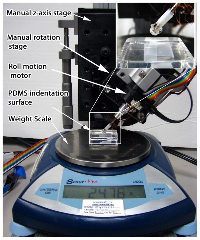
Calibration and characterization apparatus. Inset provides close up of hemispherical tip sensor contact with the indentation PDMS surface.
To accommodate variations in manufacturing, each sensor channel was individually characterized experimentally with respect to estimation of contact angle, Φ, and normal load F. A solid block of PDMS rubber was employed as the indentation surface for all experiments, rather than a rigid surface, thus providing an approximation to tissue contact.
B. Characterization of Contact Orientation
The sensor is designed to encode the contact angle via the angular difference between the peaks from each respective pressure-sensitive channel. Thus, the following procedure was employed to experimentally characterize the sensor’s capability of measuring contact angle:
The sensor is brought into contact with the PDMS indentation surface at a given contact angle and preloaded using the manual z-axis stage.
Data from all three sensors and the encoder position is recorded as the sensor undergoes a full rotation about its roll axis. Scale readings are recorded at two degree intervals. The point of contact between the hemispherical tip sensor and the indented surface is lubricated to encourage slip and mimic real tissue contact mechanics.
Recorded data is postprocessed to locate the peaks from each channel and so compute contact angle.
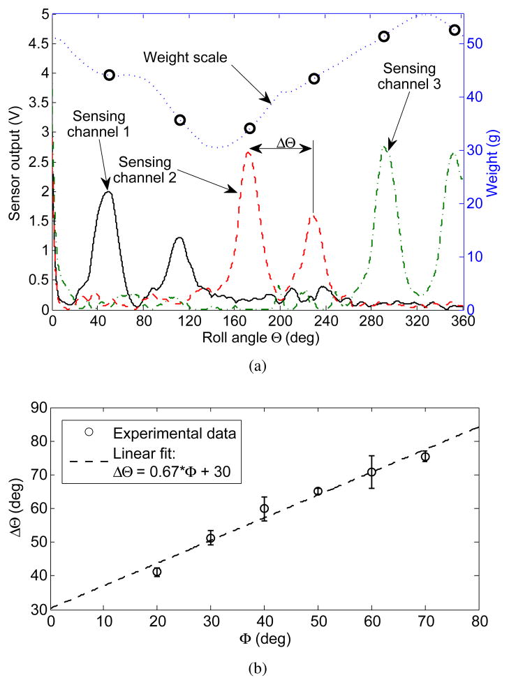
Typical data from the characterization procedure is shown in Fig. 8(a). Peaks from each sensor channel are detected using a 2Hz cut-off frequency lowpass Butterworth filter and a watershed-inspired peak detection algorithm. This method proved robust to a variety of signal conditioning electronics configurations and sensor prototypes.
Fig. 8.
Results of automatic peak detection. (a) sample recorded data set at contact angle Φ = 40°. (b) Linear relationship and statistical fit between contact angle and spatial separation between channels. Error bars indicate one standard deviation and are computed using three data points.
Hemispherical sensor contact angle is correlated to the peak separation ΔΘ, and the entire experimental map of contact angles Φ ∈ [20°, 70°] is experimentally computed, and shown in Fig. 8(b). By design, the dependence is linear, however, with a slope of 0.67, it is half of the designed slope of . This is due to a number of factors. These include that the sensing microchannels have a finite thickness, need to be sufficiently separated from their neighboring channels to avoid coupling, and that their midpoint does not intersect the roll axis of the hemispherical tip sensor, see Fig. 6(c).
The variation in weight scale measurements with roll angle arises from misalignment between the hemispherical tip sensor, delivery cannula, and the motor axes, as well as, an uneven molded surface of the hemispherical tip due to manufacturing imperfections.
The normal reaction force can only be computed from sensor measurements at the peaks, when the contact patch is centered directly on the microchannel. In general, the amplitude of each peak is strongly correlated to the weight scale measurements, with the most obvious exception being sensing channel 2. Albeit being one continuous channel, slight thinning of the PDMS layer covering a portion of the channel or a small protrusion in the hemispherical tip substrate, thereby creating a stress concentration, can result in that area being much more sensitive to normal load. Given these possible manufacturing inconsistencies, the sensing channels are next calibrated for their sensitivity to contact load F.
C. Characterization of Contact Load Sensitivity
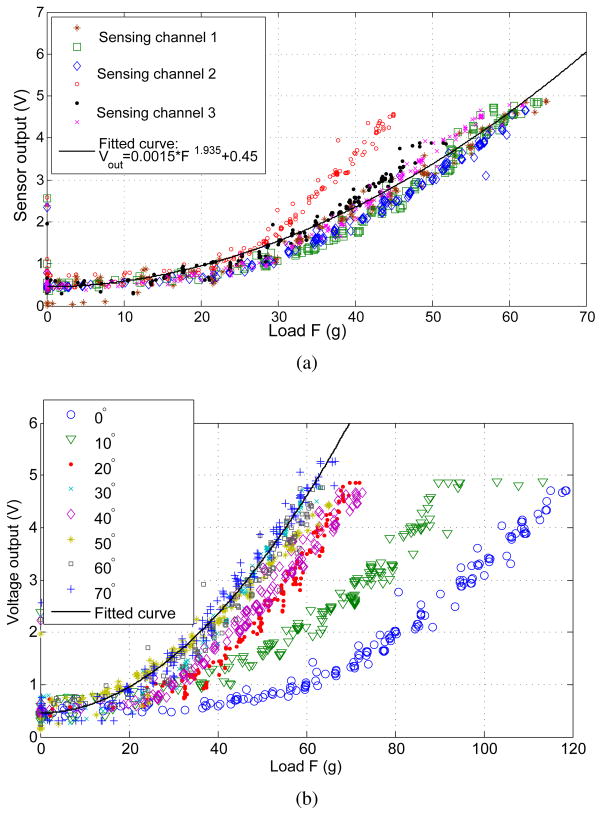
In performing experimental characterization of the microchannel sensitivity, we seek to investigate the variation of behavior both across all channels and as a function of contact angle along one channel. The sensitivity data is obtained via indentation experiments, where the contact patch is kept directly over the sensing channel and the reaction load F is varied manually via the z-axis stage. Indentation results for all sensing channels at a contact angle of 40° are shown in Fig. 9(a) and show general agreement with each other, with the exception of a single set of data from channel 2. This data is consistent with Fig. 8(a), as discussed above. The relationship between sensor readings and load is nonlinear, as expected, a fact previously addressed in [10]. Given the curvilinear geometry and unknown contact mechanics, however, an analytical treatment of sensitivity is beyond the scope of this paper. Thus, the experimental data has been fit to the power equation:
| (7) |
with a fit quality of R2 = 0.897. Note that the outlier data of channel 2 does little to affect the overall quality of the fit. Using the same data and inverting (7), we calculate the numerical fit to give an estimate of the experimental load F to within a mean accuracy of ∓4 g, and standard deviation of σ = 3.5 g, with the maximum error being 23.14 g.
Fig. 9.
Hemispherical tip sensor indentation results. (a) Across all sensing channels at 40° contact angle. (b) Along channel 1 at various contact angles. Statistical power fit equation overlayed over both data sets shows reasonable agreement to within ∓10 g of weight scale data.
Furthermore, to investigate the variation of channel sensitivity at different angles of contact, indentation data is taken along channel 1 while varying Φ, shown in Fig. 9(b). Overlaying (7) on these curves, we again observe good agreement with the exception of outlying data observed at very shallow contact angles, thus limiting the range of sensor operation to contact angles of Φ ∈ [20°, 70°]. The reason for this decrease in sensitivity lies in the change in contact mechanics closer to the axis of the hemispherical tip. The manufacturing technique currently results in extra PDMS material added where the tool insertion port would be, shown in the inset of Fig. 6(c), resulting in more contact load distributed over this area as opposed to acting over the sensing channels. Furthermore, given that the insertion port will always be a boundary condition for any such sensing hemispherical design, its behavior is likely to differ in this region, thus requiring a separate calibration curve. For the purposes of this work, the sensor operating range will be limited to the range stated above. Hence, considering only the experimental curves with Φ > 20°, the numerical fit is found to yield accurate load force estimates to within an absolute mean error of ∓3.16 g, and standard deviation of σ = 2.37 g, with the maximum error being 17.8 g.
IV. Experimental Validation
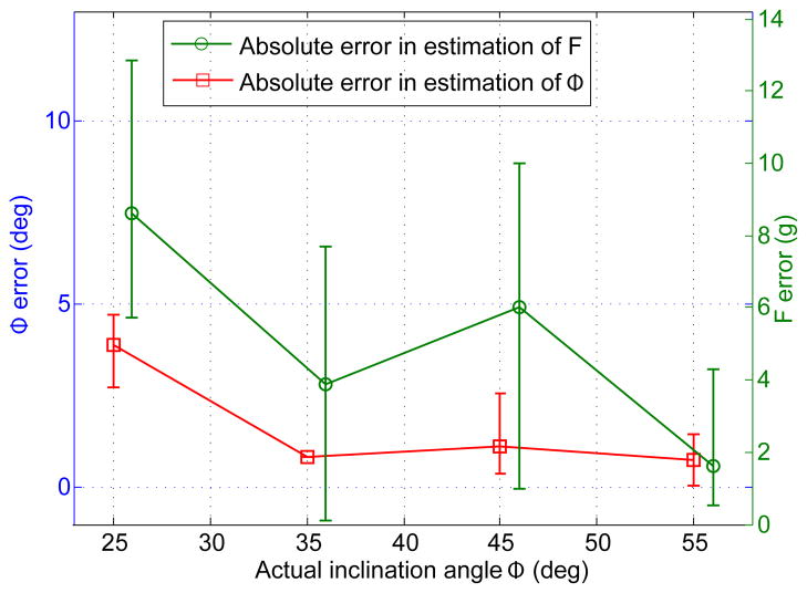
To validate sensor performance, a set of ten experiments on the characterization stage of Fig. 7 was conducted. For these experiments, the sensor voltage outputs were recorded for contact angle values (Φ = {25, 35, 45, 55} degrees) that were not employed during sensor characterization. Contact angle Φ and load F were computed from signal peak magnitudes and peak separation. For the purpose of minimizing the necessary roll angle in a surgical setting, the roll motion of the sensor was limited to a range of 150°, since any two peaks of the sensor voltage output are strictly required to determine the contact configuration. Also, although the equation for peak separation is defined for the signal maxima generated by the same sensing channel, the peak separation of two neighboring channels will follow a similar linear trend. In particular, since sensing channel geometry repeats itself every 120° of axial roll, the peak separation of neighboring sensors is given by
| (8) |
Statistical analysis of the error, shown in Fig. 10, illustrates that, overall, estimation of contact angle, Φ, is quite accurate yielding an estimate that is on average ∓2° offset from the actual angle. In contrast, force estimate is less accurate with an average offset of ∓5.27 g. This is to be expected since force estimation depends on the signal magnitude measured at a single roll angle, while estimation of contact angle is computed using the angular separation of two data points, regardless of their absolute magnitudes, thus making this measurement less susceptible to signal noise.
Fig. 10.
Estimation error for contact angle (left y-axis) and force (right y-axis) based on ten sensor validation experiments. Each data point represents mean error from three experiments conducted at different loads, along with maximum and minimum values of absolute error. Note that F error data has been slightly offset on the x-axis for clarity. The datapoint missing an upper and lower bound indicates data from a single experiment.
V. Conclusions and Future Work
A novel soft contact angle and force sensor for surgical robotic applications has been proposed, prototyped, and validated. The sensor uses an arrangement of pressure sensitive conductive microchannels embedded in a flexible polymer layer to encode contact angle and force as a function of sensor roll angle. Experimental results have shown that it can estimate contact angle to within ∓2° and contact force to within ∓6 g, on average.
A number of issues can be addressed to improve these results. These include enhancing the manufacturing molding process to result in a more uniform PDMS layer and to minimize the variability of channel sensitivity both across multiple channels and along each one.
Alternatively, the hemispherical tip sensor could be characterized in detail, such that a separate characterization curve for each channel and several points along each channel would be recorded and employed for force estimation. An additional manufacturing challenge is the integration of a tool lumen into the sensor design.
Since actual tissue is softer than the indentation PDMS surface used for channel characterization, tissue forces on the sensor are expected to be less than those measured thus requiring improved sensitivity from each sensing channel. This can be achieved either through electronic amplification, along with noise reduction techniques, or through the addition of secondary channel geometry, in order to subject more conductive microchannel area to the contact load.
Acknowledgments
This work was supported by the National Institutes of Health under grants R01HL073647 and R01HL087797.
Contributor Information
Veaceslav Arabagi, Email: Veaceslav.Arabagi@childrens.harvard.edu, Cardiovascular Surgery, Children’s Hospital Boston, Harvard Medical School, Boston, MA, 02115, USA.
Andrew Gosline, Email: Andrew.Gosline@childrens.harvard.edu, Cardiovascular Surgery, Children’s Hospital Boston, Harvard Medical School, Boston, MA, 02115, USA.
Robert J. Wood, Email: rjwood@eecs.harvard.edu, School of Engineering and Applied Sciences and the Wyss Institute for Biologically Inspired Engineering, Harvard University.
Pierre E. Dupont, Email: Pierre.Dupont@childrens.harvard.edu, Cardiovascular Surgery, Children’s Hospital Boston, Harvard Medical School, Boston, MA, 02115, USA.
References
- 1.Huang J, Triedman J, Vasilyev NV, Suematsu Y, Cleveland R, Dupont PE. Imaging artifacts of medical instruments in ultrasound-guided interventons. J Ultrasound in Medicine. 2007;26:1303–1322. doi: 10.7863/jum.2007.26.10.1303. [DOI] [PubMed] [Google Scholar]
- 2.Gosline AH, Vasilyev NV, Butler E, Folk C, Cohen A, Chen R, Lang N, del Nido PJ, Dupont PE. Percutaneous intracardiac beating-heart surgery using metal mems tissue approximation tools. Int J Robotics Research. 2012;30(9):1081–1093. doi: 10.1177/0278364912443718. [DOI] [PMC free article] [PubMed] [Google Scholar]
- 3.Kesner SB, Howe RD. Force control of flexible catheter robots for beating heart surgeryin. Proc IEEE Int Conf Robot Autom. 2011 doi: 10.1109/ICRA.2011.5979690. [DOI] [PMC free article] [PubMed] [Google Scholar]
- 4.Yip M, Yuen SG, Howe RD. A robust uniaxial force sensor for minimally invasive surgery. IEEE Trans Biomed Eng. 2010;57:1008–1011. doi: 10.1109/TBME.2009.2039570. [DOI] [PMC free article] [PubMed] [Google Scholar]
- 5.Ataollahi A, Schaeffter T, Razavi R, Seneviratne L, Althoefer K. Mri-compatible intensity-modulated force sensor for cardiac catheterization procedures. IEEE Trans on Biomedical Engineering. 2011;58(3):721–726. doi: 10.1109/TBME.2010.2095853. [DOI] [PubMed] [Google Scholar]
- 6.Tung A, Park BH, Liang DH, Niemeyer G. Laser-machined shape memory alloy sensors for position feedback in active catheters. Sensors & Actuators: A Physical. 2008;147:83–92. doi: 10.1016/j.sna.2008.03.024. [DOI] [PMC free article] [PubMed] [Google Scholar]
- 7.Lipomi DJ, Vosgueritchian M, Tee BC-K, Hellstrom SL, Lee JA, Fx CH, Bao Z. Skin-like pressure and strain sensors based on transparent elastic films of carbon nanotubes. Nature Nanotechnology. 2011;6:788–792. doi: 10.1038/nnano.2011.184. [DOI] [PubMed] [Google Scholar]
- 8.Majidi C, Kramer R, Wood RJ. A non-differential elastomer curvature sensor for softer-than-skin electronics. Smart Materials and Structures. 2011;20:1–6. [Google Scholar]
- 9.Dickey MD, Chiechi RC, Larsen RJ, Weiss EA, Weitz DA, Whitesides GM. Eutectic gallium indium (egain): a liquid metal alloy for the formation of stable structures in microchannels at room temperature. Adv Funct Mater. 2008;18(7):10971104. [Online]. Available: http://dx.doi.org/10.1002/adfm.200701216. [Google Scholar]
- 10.Park Y, Majidi C, Cramer R, Berard P, Wood RJ. Hyperelastic pressure sensing with a liquid-embedded elastomer. Journal of Micromechanics and Microengineering. 2010;20:1–5. [Google Scholar]
- 11.Kramer R, Majidi C, Wood R. Wearable tactile keypad with stretchable artificial skin. IEEE Int. Conf. on Robotics and Automation; 2011. [Google Scholar]


