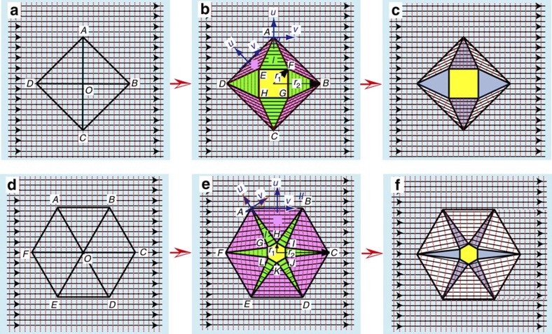
Figure 1. Principle of natural light cloaking.
Horizontal rays are incident from left to right. The red dotted vertical lines represent wavefronts when illumination is coherent. The central hidden region is marked in yellow. (a) The virtual space with straight Cartesian coordinates is filled with an isotropic background medium (marked in light blue) with a relative permeability of μb=1 and a relative permittivity of εb. The square in the virtual space is divided into four triangular sections and then transformed to the physical space by applying a homogeneous transformation in the local coordinates of each triangular section. (b) A perfect square cloak is designed by applying a coordinate transformation to open a square ‘hole’ at the centre. The wave has to propagate with infinite phase velocity in the singular anisotropic region (marked in green). (c) A four-directional square cloak with incident rays propagating horizontally. Wavefronts are perpendicular to the rays. (d) The hexagon in the virtual space is divided into six triangular sections and then transformed to the physical space by applying a homogeneous transformation in the local coordinates of each triangular section. (e) A perfect hexagonal cloak designed from coordinate transformation. (f) A six-directional hexagonal cloak with incident rays propagating horizontally. Wavefronts are perpendicular to the rays. In b and e, the cloaks require extreme and anisotropic material parameters. In c and f, the cloaks can be greatly simplified with isotropic materials while the invisibility performance is maintained in multiple directions.

