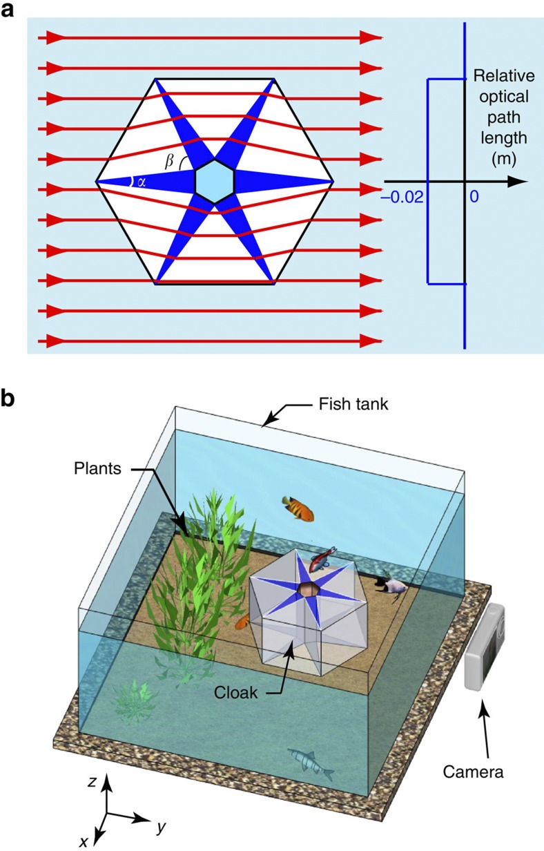
Figure 2. Experimental fabrication and set-up of the aquatic ray cloak.
(a) Ray diagram of light passing through the cloak in an aquatic environment. The background and the region in the centre (both are marked in light blue) contain water (nb=1.33). The region marked in white is air (n2=1). The region in dark blue is glass (n1=1.78) with an angle α=13°. The plot on the right shows the optical path length of the rays travelling through the cloak and those travelling straight in water (used as a reference). (b) Experimental set-up in a fish tank. The cloak is constructed with six pieces of glass with n1=1.78 (indicated in dark blue) enclosed in a hollow hexagonal container made of transparent glass.

