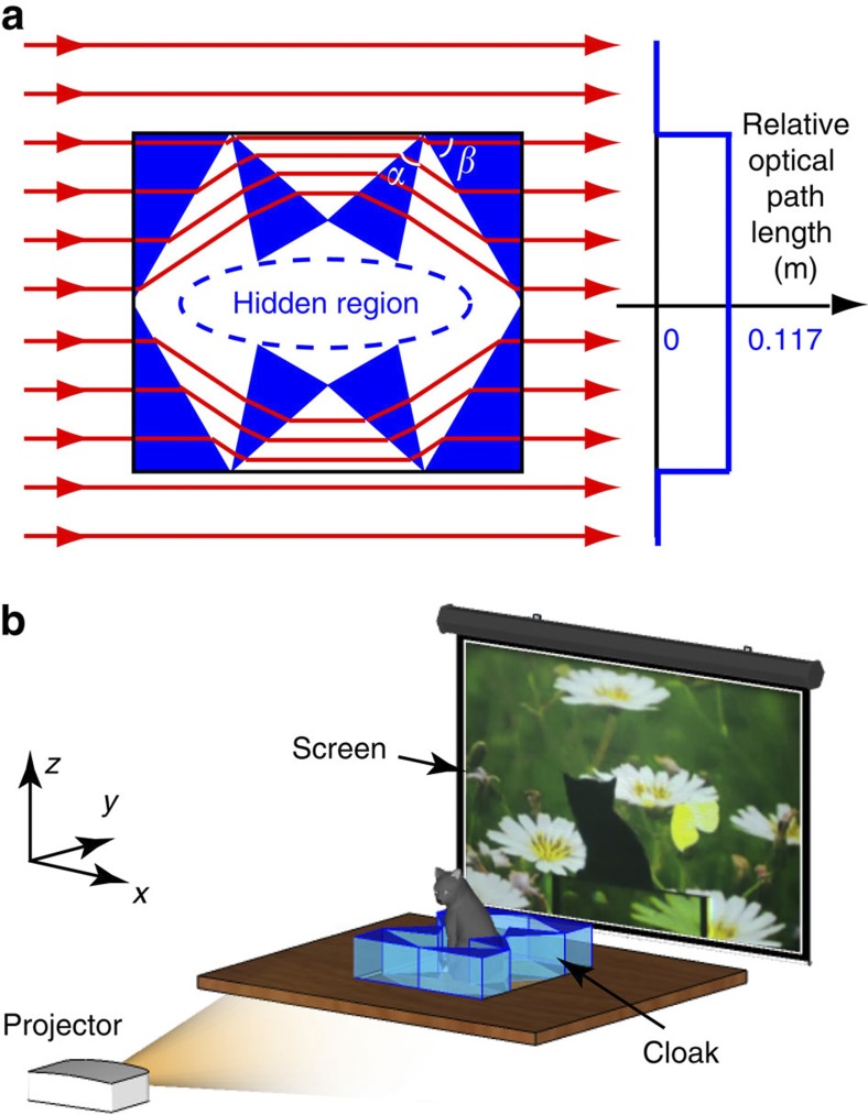
Figure 4. Experimental fabrication and set-up of the terrestrial ray cloak.
(a) Ray diagram of light passing through the cloak in a terrestrial environment. The region in dark blue is glass (n1=1.78). The other regions marked in white are air (nb=1). The angles of the pieces of glass are α=36.5° and β=60°. The cloak is 0.3 m long, 0.26 m wide and 0.07 m high. The plot on the right shows the optical path length of the rays travelling through the cloak and those travelling straight in air (used as a reference). (b) Experimental set-up to test the cloaking performance. An office projector projects a movie through the cloak onto the screen behind the cloak. A camera (not shown here) placed behind the screen records the movie on the screen. A live cat is sitting inside the cloak.

