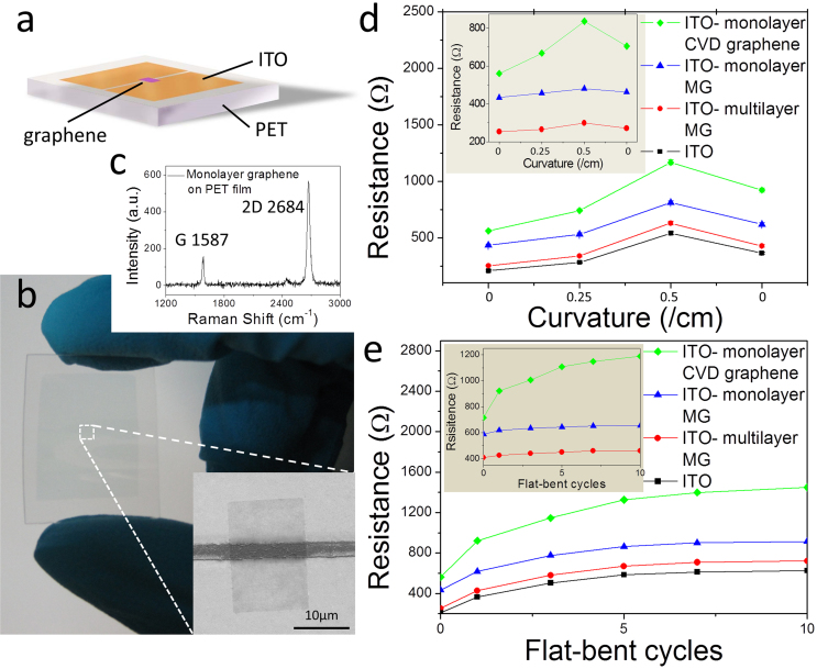
Figure 5. Bending test of the PET/ITO/graphene flexible device fabricated by selective transfer.
(a) The configuration and (b) a photograph of the PET/ITO/graphene device. The inset in (b) is the SEM image of the transferred graphene connecting the two ITO films. (c), The Raman spectrum of the transferred graphene on PET. (d), The changes in the resistance of the four devices as a function of the bending radius. (e), Resistance of the devices with different flat-bent cycles. The insets in (d) and (e) show the results with the resistance variation of the ITO films removed from (d) and (e), respectively.

