Abstract
We present an aberration cancelling optical design for a reflective adaptive optics - optical coherence tomography (AO-OCT) retinal imaging system. The optical performance of this instrument is compared to our previous multimodal AO-OCT/AO-SLO retinal imaging system. The feasibility of new instrumentation for improved visualization of microscopic retinal structures is discussed. Examples of images acquired with this new AO-OCT instrument are presented.
OCIS codes: (110.4500) Optical coherence tomography, (010.1080) Active or adaptive optics, (220.1000) Aberration compensation, (170.0110) Imaging systems, (170.4470) Ophthalmology, (120.3890) Medical optics instrumentation
1. Introduction
Over the last decade, adaptive optics (AO) retinal imaging instruments have made possible routine imaging of in vivo human retina at the cellular scale [1–5]. However, the first reports of in vivo imaging of the rod photoreceptor mosaic have only recently been published [6–8]. This improved performance and resolution of AO systems can be attributed to implementation of aberration cancelling design strategies for reflective AO imaging instruments [9–11].
We previously described several AO-OCT system designs, including a combined AO-OCT/AO-SLO instrument, that uses an “in-plane” optical design of the AO-OCT sample arm [3,12,13]. Here we present progress on the development of the next generation of AO-OCT systems, implementing an “off-plane” design using reflective optics. The basic principle of aberration cancelling is to eliminate the most dominant aberration, astigmatism, by using two mirrors with orthogonal rotation [14], so called “off-plane” design. A similar design strategy has been implemented recently in AO-SLO and AO-OCT systems for retinal imaging [8, 15–17]. An interesting alternative to “off-plane” design achieved by use of toroidal mirrors for AO-OCT systems has also been proposed recently [18,19].
Our new AO-OCT system “off-plane” sample arm design was created using optimization methods available in optical design software that allowed for simultaneous minimization of the wavefront aberrations and the pupil wanders. This allowed for diffraction-limited optical design over a 3° x 3° field of view with 8 diopter vergence correction range ( ± 4 Diopter). Pupil wander at the eye plane is reduced under 0.1mm (1.5%) of its pupil size (6.8mm).
2. Optical design
Figure 1 shows screenshots of the 3D layout of the imaging optics of the AO-OCT sample arm as visualized by optical design software (Zemax). Similar to our final version of the “in- plane” original design, we used a cascade of focal telescopes (created by pairs of spherical mirrors) to produce conjugate planes of the eye pupil with all key optical components, including X and Y scanning mirrors, wavefront correctors and a Hartmann-Shack (H-S) wavefront sensor (which uses the OCT imaging light for wavefront reconstruction).
Fig. 1.
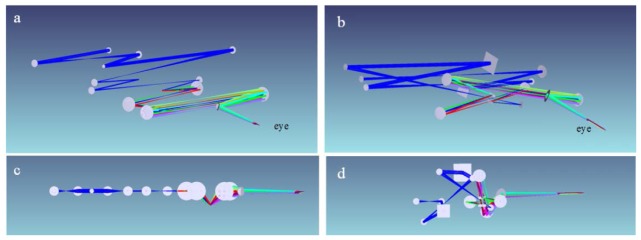
3D visualization of old “in-plane” (left) and new “off-plane” (right) afocal AO-OCT sample arm designs. Angle view of old (a) and new (b) AO-OCT sample arms. Side view of old (c) and new (d) AO-OCT sample arms.
The main difference from the previous “in-plane” system is that the current design places optical elements out of the single plane in order to minimize system residual aberration. The aberrations that affect image quality in the pupil planes are reduced by the “off-plane” design. Optical aberrations of imaging systems are responsible for reducing performance of adaptive optics. Therefore, implementation of an “off-plane” design of the optical system is critical for achieving optimum performance of the AO system and for measuring and correcting aberration of the sample, in our case the subject’s ocular aberrations. As shown in Fig. 1(a), 1(c), and Fig. 2(a) , the spherical mirrors are placed in a single plane in the old AO-OCT sample arm. Inevitably, the astigmatism is cumulated as the number of mirror-based telescopes is increased. The principle of the new AO-OCT sample arm design is to counterbalance the astigmatism by rotating the optical axis orthogonally as shown in Fig. 1(b), 1(d), and Fig. 2(b) [11]. The aberrations are counterbalanced at each corresponding spherical mirror that reflects the imaging light. This principle was maintained during the optical design and resulted in very effectively cancelled aberrations.
Fig. 2.
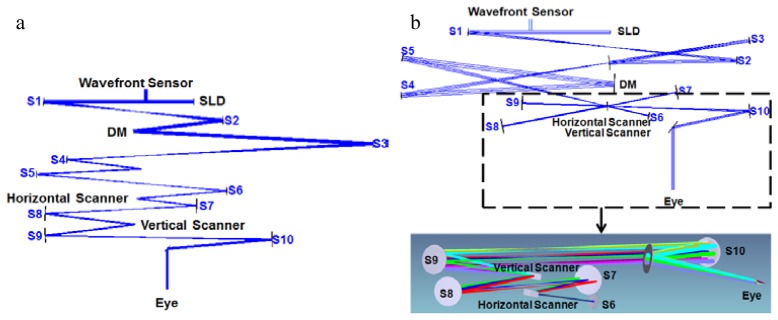
Top view of old “in-plane” (a) and new “off-plane” (b) AO-OCT sample arms. DM – Deformable mirror; SLD – Superluminescent Diode; S1-S10: Spherical mirrors.
Table 1 shows the optical design parameters and the height of each optical component. The maximum system height is limited to less than 25 cm and the minimum height is set as 5 cm from the optical table. The maximum height limit was chosen arbitrarily to limit the vertical size of the system, while the minimum height was chosen based on the mechanical dimensions of available opto-mechanical mounts. In the optical design stage, we had to accept some trade-offs in some optical parameters. For example, we had to compromise between residual wavefront error and pupil wander to meet our final specifications of the system. In our case, achieving diffraction-limited performance in our desired field of view was the main goal of the optical design. Optimization becomes easier if there is a greater range in the optical parameters. If we could, for example, vary the heights of optical components over 25 cm, the final performance could be further improved. We set up an optimization merit function that targets both residual wavefront error and pupil wander. We then found the optimum value of weights for the two merit functions to satisfy our design goal. All the angles and heights of components were allowed to vary during optimization except the angles of the deformable mirror and horizontal scanner. This is because we cannot easily change the angle of the deformable mirror and horizontal scanner. It is important to use the smallest angle between two adjacent telescopes for the effective optimization in the optical design stage. So we put the vertical scanner at the top of the horizontal scanner to minimize the astigmatism that is generated by the beam angle from the spherical mirror. As a result, we eliminated one source of wavefront aberration and achieved very small wavefront error. Table 1 summarizes the optimum heights of all the optical components that minimize the wavefront error and pupil wander. We designed the AO-OCT system to have diffraction-limited performance for the subject’s eye aberration from −4 to + 4 Diopter (Dpt) with a 3° x 3° field of view.
Table 1. Design parameters (Focal length, tilt angle of mirror and height).
| Surface # | Focal length (mm) | Angle x (degree) | Angle y (degree) | Height (cm) |
|---|---|---|---|---|
| 1 | 500 | 3.0 | 0.0 | 12.95 |
| 2 | 450 | 2.5 | 2.4 | 12.95 |
| Future DM | Flat mirror | −5.0 | −0.1 | 9.39 |
| 3 | 500 | −8.9 | −6.4 | 5.08 |
| 4 | 750 | −6.0 | −3.1 | 22.10 |
| Deformable Mirror | - | 2.0 | 0.7 | 24.38 |
| 5 | 750 | 10.1 | −4.6 | 24.64 |
| 6 | 150 | 13.1 | −6.0 | 10.67 |
| Horizontal Scanner | - | 1.0 | 0.0 | 11.43 |
| 7 | 250 | −11.0 | 1.5 | 12.95 |
| 8 | 375 | −11.0 | 0.9 | 13.21 |
| Vertical Scanner | - | −4.5 | −2.9 | 14.48 |
| 9 | 300 | 2.0 | −3.7 | 18.29 |
| 10 | 500 | −5.0 | 0.5 | 19.05 |
| 11 | Flat mirror | 39.0 | 0.7 | 18.80 |
Figure 3 shows spot diagrams of the old “in-plane” and new “off-plane” AO-OCT sample arm plotted as a function of scanning position (3° x 3°). In the prior AO-OCT design, the main aberration remaining was astigmatism. Off-axis aberration, like astigmatism, is severe in a cascaded telescope system because it accumulates as light passes through all the mirrors that are placed sequentially in a single plane. In our new AO-OCT design, geometrical spot size is reduced under the size of the Airy Disk without DM correction. Wavelengths used for design were 800 nm, 850 nm and 900 nm. Airy disk size was 2.5 μm.
Fig. 3.
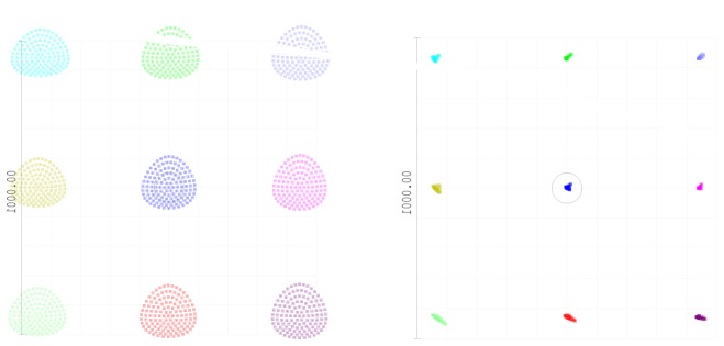
Comparison of spot diagram with Airy Disk (black circle) as a function of scanner position over 3° x 3° field for old (left) and new (right) designs. (Spot diagrams are magnified by 20 times.)
Another important benefit of an ”off-plane” optical design is reduction of pupil wander observed at the system entrance pupil plane during imaging. Minimizing this effect is critical for proper measurements and correction of wavefront error. Figure 4 shows a comparison of pupil wander for the old “in-plane” and new “off-plane” AO-OCT sample arm design plotted as a function of retinal scanning position (3° x 3°). The maximum pupil wander of our new system for 3° x 3° retinal FOV is under 0.1 mm, which is also lower than the value of the previous system: 0.65 mm.
Fig. 4.
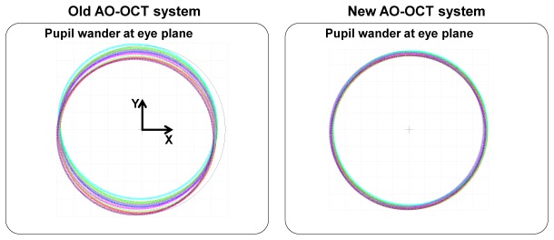
Comparisons of pupil wander as a function of imaging beam position in x and y axis (scanning angle over 3° x 3°) for old (left) and new (right) AO-OCT designs. The pupil shapes represent the instrument’s pupil as observed at the eye’s pupil for several scanning angles.
Pupil wander impairs performance of an AO system. In our system, the exposure time of the wavefront sensor is on the order of 30-50 ms; thus, different parts of the eye pupil are sampled during single wavefront data acquisition, which “blurs” measured wavefronts. This can also result in creation of periodic modulations of measured wavefront as different parts of the pupil have different wavefronts.
3. Modeling of system performances over an 8 Dpt vergence range
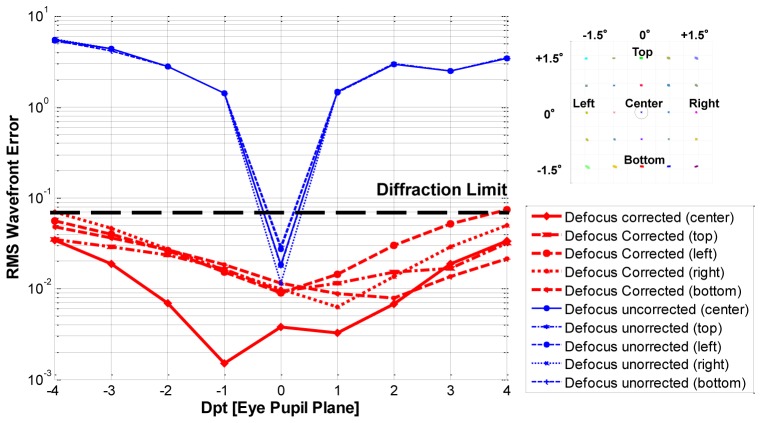
We modeled the ability of the DM to correct the residual system aberrations. To quantify the correction and maximum stroke of the DM, we generated defocus errors on the eye pupil. Defocus values from −4 to + 4 Dpt are applied and corrected by the DM. This corresponds to evaluating performance of our system for imaging patients with different refractive error. The wavefront sensor measures the residual system aberrations for DM correction. Figure 5 shows the RMS wavefront error of the OCT system when the defocus is applied (blue line) and corrected (red line) for 3° x 3° FOV. The design results demonstrate that the new AO-OCT system has diffraction-limited performance for all the defocus generated with DM correction. The maximum DM stroke needed to correct ± 4 Dpt defocus was ± 9.2 µm, well below the deformation range of the AlpAO mirror ( ± 22 µm) used in our system.
Fig. 5.
RMS wavefront error of our “off-plane” OCT system for ± 4 Dpt defocus and corresponding DM correction (log scale) for 3° x 3° FOV. Deformable mirror was fixed for all retinal positions.
Another important improvement of our new “off-plane” AO-OCT system is the circular pupil shape during the correction of a subject’s eye aberrations. The old “in-plane” system has astigmatism as the dominant system aberration as shown in Fig. 6 . The new system has spherical aberration rather than astigmatism as the dominant residual aberration.
Fig. 6.

Through focus spot diagram of the old “in-plane” (left) and new “off-plane” (right) AO-OCT design
This difference of dominant aberration allows the DM to correct aberrations without changing the shape of the eye pupil elliptically in the new AO-OCT system. The shape of the DM in the old AO-OCT was elliptical when it corrected the aberration of the eye because of the system astigmatism. Figure 7 shows the shape of the pupil at the eye plane. The shape of the pupil still remains circular when the DM corrects 4 Dpt of aberration from the eye in the new “off- plane” AO-OCT system. But the shape of the pupil in the old “in-plane” AO-OCT system becomes elliptical when it corrects the aberration of the subject’s eye using the DM.
Fig. 7.
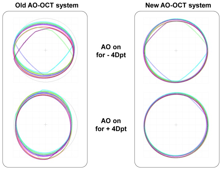
Pupil wander and shape at the eye plane when the AO is off and on is shown for old “in-plane” (left) and new “off-plane” (right) AO-OCT designs (3° x 3° FOV).
An elliptical pupil shape makes the lateral resolution of sagittal and tangential foci different from each other. This results in a loss of resolving power at the sagittal focal point when the DM works because of the system astigmatism. Figure 8 shows the spot diagram at the retinal plane with the Airy Disk (black circle) when the AO is ON for the new AO-OCT design (3° x 3° FOV) for different values of subject refractive error ( ± 4 Dpt). The deformable mirror was modeled as fixed for all the retinal positions with the “static” correction of defocus, astigmatism and coma.
Fig. 8.

Spot diagram at the retinal plane with Airy Disk (black circle) when the AO is on for new AO-OCT design (3° x 3° FOV) for different values of subject refractive error ( ± 4 Dpt). The deformable mirror was fixed for all the retinal positions with the correction of defocus, astigmatism and coma. Spot diagrams are magnified by 20 times.
4. Experiment
Figure 9 shows the experimental setup of the new “off-plane” AO-OCT sample arm. In the optical design, we used a series of afocal telescopes to image the eye’s pupil on all key optical components, including vertical and horizontal scanning mirrors, wavefront corrector (deformable mirror, DM), the Hartmann-Shack wavefront sensor and the fiber collimator for light delivery. A superluminescent diode (SLD, T840-HP) was used as the light source. The center wavelength was 840 nm and the bandwidth was 112 nm with output power of 16 mW. The light was split by an 80/20 fiber directional coupler into the reference and sample arms of the OCT system’s Michelson interferometer, respectively.
Fig. 9.
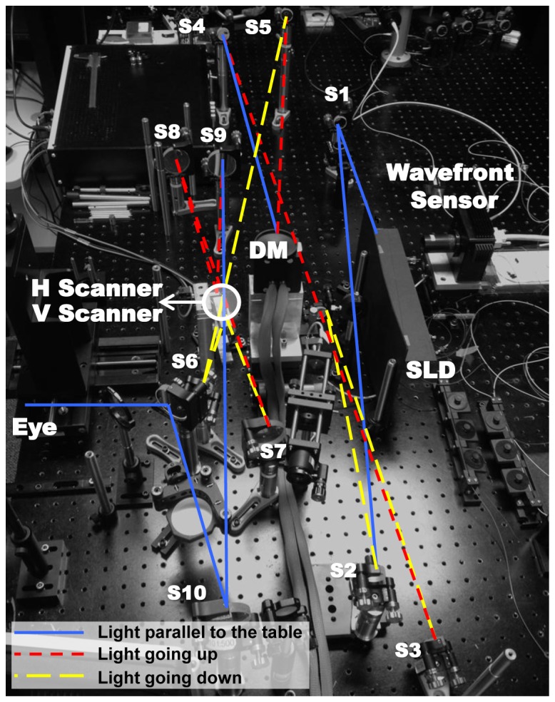
Experimental setup of new afocal AO-OCT sample
The OCT acquisition engine was similar to the one we described previously for our phase-variance OCT instrument [20]. The OCT GPU-based acquisition software used in our instrument has been developed and shared by Sarunik’s group from SFU [21]. Light back-scattered from the retina was combined with light from the reference arm and the spectral fringes were acquired in the detection channel of the OCT spectrometer. A water cuvette placed in the reference arm approximately matched dispersion induced by the human eye in the sample arm; any remaining dispersion mismatch was corrected by Fourier-domain OCT reconstruction software [3]. Each solid and dotted line represents the direction of the light. The light beam travels up and down to minimize the aberration of the system and the pupil wander at the eye plane. In our old “in-plane” AO-OCT system, the aberrations were cumulated as light passed through all the spherical mirrors because it was designed in a single plane. In our new “off-plane” AO-OCT system the aberrations are counterbalanced at each corresponding spherical mirror that reflects the light.
4.1 Imaging of the resolution chart
Figure 10 shows an OCT en-face projection image of a resolution chart acquired by the new AO-OCT system when the deformable mirror was replaced by a flat mirror. Thus, no AO correction in the sample arm was performed and system optical performance could be evaluated. We used an eye model that has an achromatic lens with focal length of 30 mm to image the resolution chart. The calculated spot size (defined as the 1/e2 width: distance between the two points on the marginal distribution that are 1/e2 = 0.135 times the maximum value) was 7.45 µm with the eye model. Note that our system resolved the small bars that have a gap width of 3.11 µm without correcting residual aberrations of the imaging system (no AO correction) what confirms its diffraction-limited performance.
Fig. 10.
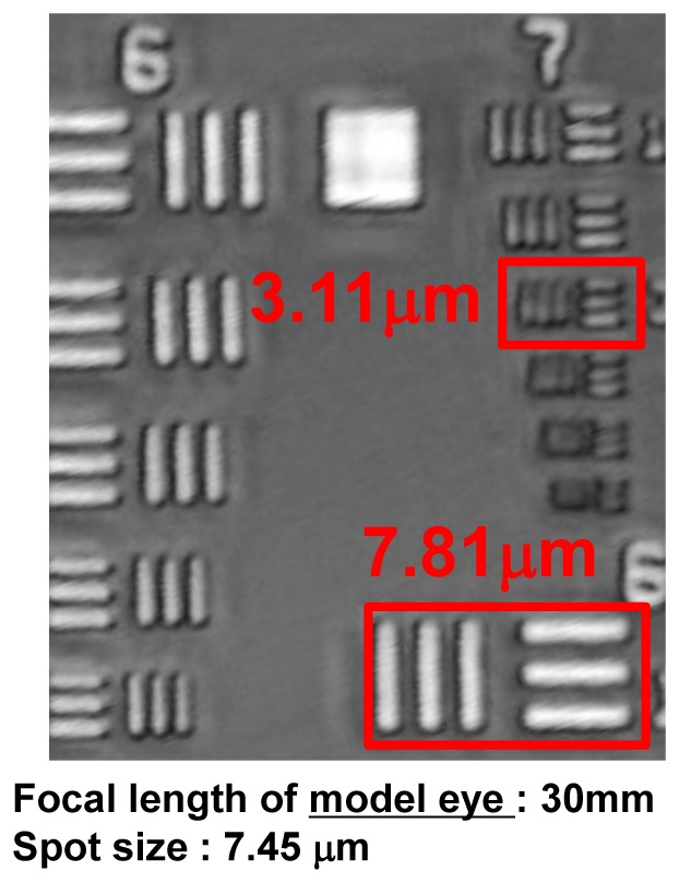
En-face OCT projection image of resolution chart without AO.
In the eye, however, we should consider the shorter focal length and the material of eye which has an average refractive index of 1.34. Based on this result, the corresponding diffraction-limited lateral resolution of our new “off- plane” AO-OCT system in the human eye should be below 2 µm.
4.2 In-vivo imaging of the human retina
As an example of our AO-OCT system capabilities we present a volumetric AO-OCT data set acquired from a healthy 61-year-old volunteer with minimum refractive error. Written informed consent was obtained before imaging under protocols approved by the Institutional Review Board of the University of California Davis.
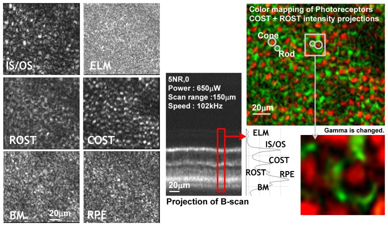
Optical power on the cornea was 650 µW and the OCT acquisition speed was 102 kHz with a 0.75° x 0.75° FOV scanning range on the retina. Figure 11 shows representative C-scans and B-scan projections reconstructed from a single volumetric AO-OCT data set. The focus of the AO-OCT system was set to the depth of the IS/OS junction. The adjacent photoreceptor layer bands from the volume data were separated. Additionally, there was improved resolution and contrast of en-face projection views of photoreceptor sub-cellular layers extracted from volumetric scans compared to our previous AO-OCT system. Each of the extracted C-scans was created by projecting intensities within the thickness of each layer (< 10 µm). The difference between morphology of each sub layer caused by different microscopic components can be easily observed. Note that the bright structures seen on projection view of cone outer segment tips (COST) and rod outer segments tips (ROST) layers are complimentary to each other which is visualized by lack of color mixing in the combined color-coded view of both layers.
Fig. 11.
Intensity projections of different retinal layers from a single AO-OCT volume focused on outer retina. ELM – external limiting membrane; IS/OS – photoreceptors inner/outer segment junction, COST – cone outer segments tips; ROST rod outer segments tips, RPE – retinal pigment epithelium, BM – Bruch's membrane
We propose that the structures seen in ROST projection view are the rod photoreceptors arranged in the mosaic surrounding cone photoreceptors. We think that our inability to clearly resolve the rod photoreceptor mosaic is due to the creation of speckle by the coherent detection nature of OCT. This effect is similar to previously described effects observed in AO-SLO systems with partially coherent light illumination [22]. Note that intensity projections of ELM, BM and RPE look similar due to the presence of scattering structures smaller than the lateral resolution of our system resulting in a uniform speckle field in these layers.
5. Conclusions
An off-plane AO-OCT system was designed and successfully implemented allowing minimization of the wavefront error and pupil wander to result in better resolution and retinal image quality. Counterbalancing of wavefront errors and minimizing pupil wander were possible using a conventional cascade of focal telescopes by rotating the telescopes orthogonally. Increased lateral resolution allowed visualization of 3D morphology of cone and rod photoreceptor layers. Note that despite the high axial resolution of our AO-OCT system which allows us to separate axially the band of cone outer segment tips from rod outer segment tips, the coherent artifact (speckle) might be responsible for reducing visibility of the rod mosaic (rod diameters are in the order of our system speckle diameter). This is why one should be careful if comparing AO-SLO with AO-(Fd-OCT) data sets due to different acquisition planes and measured signal origins as well as image processing.
To take full advantage of the improved resolution of our system we plan to implement retinal motion correction techniques and spectral speckle reduction schemes. This will allow averaging of AO-OCT data sets to reduce speckle contrast seen in single AO-OCT volumes.
Acknowledgments
We gratefully acknowledge the contributions of VSRI UC Davis lab members, especially by Ravi Jounal for help with AO software. Support of Marinko V. Sarunik and Yifan Jian from SFU Vancouver, Canada by sharing BORG GPU based OCT image acquisition software is appreciated. This research was supported by the National Eye Institute (EY 014743) and Research to Prevent Blindness (RPB).
References and links
- 1.Liang J., Williams D. R., Miller D. T., “Supernormal vision and high-resolution retinal imaging through adaptive optics,” J. Opt. Soc. Am. A 14(11), 2884–2892 (1997). 10.1364/JOSAA.14.002884 [DOI] [PubMed] [Google Scholar]
- 2.Roorda A., Romero-Borja F., Donnelly III W., Queener H., Hebert T. J., Campbell M. C. W., “Adaptive optics scanning laser ophthalmoscopy,” Opt. Express 10(9), 405–412 (2002). 10.1364/OE.10.000405 [DOI] [PubMed] [Google Scholar]
- 3.Zawadzki R. J., Jones S. M., Olivier S. S., Zhao M., Bower B. A., Izatt J. A., Choi S., Laut S., Werner J. S., “Adaptive-optics optical coherence tomography for high-resolution and high-speed 3D retinal in vivo imaging,” Opt. Express 13(21), 8532–8546 (2005). 10.1364/OPEX.13.008532 [DOI] [PMC free article] [PubMed] [Google Scholar]
- 4.Godara P., Dubis A. M., Roorda A., Duncan J. L., Carroll J., “Adaptive optics retinal imaging: emerging clinical applications,” Optom. Vis. Sci. 87(12), 930–941 (2010). 10.1097/OPX.0b013e3181ff9a8b [DOI] [PMC free article] [PubMed] [Google Scholar]
- 5.Williams D. R., “Imaging single cells in the living retina,” Vision Res. 51(13), 1379–1396 (2011). 10.1016/j.visres.2011.05.002 [DOI] [PMC free article] [PubMed] [Google Scholar]
- 6.Doble N., Choi S. S., Codona J. L., Christou J., Enoch J. M., Williams D. R., “ In vivo imaging of the human rod photoreceptor mosaic,” Opt. Lett. 36(1), 31–33 (2011). 10.1364/OL.36.000031 [DOI] [PMC free article] [PubMed] [Google Scholar]
- 7.Dubra A., Sulai Y., Norris J. L., Cooper R. F., Dubis A. M., Williams D. R., Carroll J., “Noninvasive imaging of the human rod photoreceptor mosaic using a confocal adaptive optics scanning ophthalmoscope,” Biomed. Opt. Express 2(7), 1864–1876 (2011). 10.1364/BOE.2.001864 [DOI] [PMC free article] [PubMed] [Google Scholar]
- 8.Merino D., Duncan J. L., Tiruveedhula P., Roorda A., “Observation of cone and rod photoreceptors in normal subjects and patients using a new generation adaptive optics scanning laser ophthalmoscope,” Biomed. Opt. Express 2(8), 2189–2201 (2011). 10.1364/BOE.2.002189 [DOI] [PMC free article] [PubMed] [Google Scholar]
- 9.Chen D. C., Jones S. M., Silva D. A., Olivier S. S., “High-resolution adaptive optics scanning laser ophthalmoscope with dual deformable mirrors,” J. Opt. Soc. Am. A 24(5), 1305–1312 (2007). 10.1364/JOSAA.24.001305 [DOI] [PubMed] [Google Scholar]
- 10.Burns S. A., Tumbar R., Elsner A. E., Ferguson D., Hammer D. X., “Large-field-of-view, modular, stabilized, adaptive-optics-based scanning laser ophthalmoscope,” J. Opt. Soc. Am. A 24(5), 1313–1326 (2007). 10.1364/JOSAA.24.001313 [DOI] [PMC free article] [PubMed] [Google Scholar]
- 11.Gómez-Vieyra A., Dubra A., Malacara-Hernández D., Williams D. R., “First-order design of off-axis reflective ophthalmic adaptive optics systems using afocal telescopes,” Opt. Express 17(21), 18906–18919 (2009). 10.1364/OE.17.018906 [DOI] [PMC free article] [PubMed] [Google Scholar]
- 12.Zawadzki R. J., Cense B., Zhang Y., Choi S. S., Miller D. T., Werner J. S., “Ultrahigh-resolution optical coherence tomography with monochromatic and chromatic aberration correction,” Opt. Express 16(11), 8126–8143 (2008). 10.1364/OE.16.008126 [DOI] [PMC free article] [PubMed] [Google Scholar]
- 13.Zawadzki R. J., Jones S. M., Pilli S., Balderas-Mata S., Kim D. Y., Olivier S. S., Werner J. S., “Integrated adaptive optics optical coherence tomography and adaptive optics scanning laser ophthalmoscope system for simultaneous cellular resolution in vivo retinal imaging,” Biomed. Opt. Express 2(6), 1674–1686 (2011). 10.1364/BOE.2.001674 [DOI] [PMC free article] [PubMed] [Google Scholar]
- 14.Gardner J. L., “Astigmatism cancellation in spectroradiometry,” Metrologia 28(3), 251–254 (1991). 10.1088/0026-1394/28/3/029 [DOI] [Google Scholar]
- 15.A. Dubra, A. Gómez-Vieyra, D. Malacara-Hernández, and D. R. Williams, “First-order design of off-axis reflective ophthalmic adaptive optics systems using afocal telescopes,” in Frontiers in Optics, OSA Technical Digest (CD) (Optical Society of America, 2009), paper JWF4. 10.1364/AOPT.2009.JWF4 [DOI] [PMC free article] [PubMed]
- 16.Dubra A., Sulai Y., “Reflective afocal broadband adaptive optics scanning ophthalmoscope,” Biomed. Opt. Express 2(6), 1757–1768 (2011). 10.1364/BOE.2.001757 [DOI] [PMC free article] [PubMed] [Google Scholar]
- 17.Hammer D. X., Ferguson R. D., Mujat M., Patel A., Plumb E., Iftimia N., Chui T. Y. P., Akula J. D., Fulton A. B., “Multimodal adaptive optics retinal imager: design and performance,” J. Opt. Soc. Am. A 29(12), 2598–2607 (2012). 10.1364/JOSAA.29.002598 [DOI] [PMC free article] [PubMed] [Google Scholar]
- 18.L. Zhuolin, O. P. Kocaoglu, R. S. Jonnal, Q. Wang, and D. T. Miller, “Performance of an off-axis ophthalmic adaptive optics system with toroidal mirrors.” In Adaptive Optics: Methods, Analysis and Applications. Optical Society of America, (2011). [Google Scholar]
- 19.Z. Liu, O. Kocaoglu, Q. Wang, and D. T. Miller, “Design and validation of a toroidal-based ophthalmic adaptive optics system,” in Imaging and Applied Optics, J. Christou and D. Miller, eds., OSA Technical Digest (online) (Optical Society of America, 2013), paper OM4A.2. [Google Scholar]
- 20.Kim D. Y., Fingler J., Werner J. S., Schwartz D. M., Fraser S. E., Zawadzki R. J., “In vivo volumetric imaging of human retinal circulation with phase-variance optical coherence tomography,” Biomed. Opt. Express 2(6), 1504–1513 (2011). 10.1364/BOE.2.001504 [DOI] [PMC free article] [PubMed] [Google Scholar]
- 21.Jian Y., Wong K., Sarunic M. V., “Graphics processing unit accelerated optical coherence tomography processing at megahertz axial scan rate and high resolution video rate volumetric rendering,” J. Biomed. Opt. 18(2), 026002 (2013). 10.1117/1.JBO.18.2.026002 [DOI] [PubMed] [Google Scholar]
- 22.Putnam N. M., Hammer D. X., Zhang Y., Merino D., Roorda A., “Modeling the foveal cone mosaic imaged with adaptive optics scanning laser ophthalmoscopy,” Opt. Express 18(24), 24902–24916 (2010). 10.1364/OE.18.024902 [DOI] [PMC free article] [PubMed] [Google Scholar]


