Abstract
In this paper we present a multimodal device for imaging fundus of human eye in vivo which combines functionality of autofluorescence by confocal SLO with Fourier domain OCT. Native fluorescence of human fundus was excited by modulated laser beam (λ = 473 nm, 20 MHz) and lock-in detection was applied resulting in improving sensitivity. The setup allows for acquisition of high resolution OCT and high contrast AF images using fluorescence excitation power of 50-65 μW without averaging consecutive images. Successful functioning of constructed device have been demonstrated for 8 healthy volunteers of different age ranging from 24 to 83 years old.
OCIS codes: (110.0110) Imaging systems; (170.4460) Ophthalmic optics and devices; (170.4500) Optical coherence tomography; (170.5755) Retina scanning; (170.6280) Spectroscopy, fluorescence and luminescence
1. Introduction
Imaging of human eye in vivo by measuring fundus autofluorescence (FAF) is a diagnostic tool commonly used in ophthalmology. It provides complementary information to that gathered by other imaging techniques like fluorescein angiography and optical coherence tomography (OCT). FAF imaging systems are similar to regular scanning laser ophthalmoscopes (SLO) equipped with fluorescence detection of ICG or fluorescein. The main difference is in the level of detection sensitivity, optical powers and optical frequencies of excitation and fluorescence light [1–4]. Typical powers used for excitation of fundus autofluorescence in vivo are above 200 μW [3, 4] and images are obtained by averaging usually of 4-32 frames [5].
Optical Coherence Tomography OCT is a rapidly developing imaging technique [6]. It allows for cross-sectional imaging of weakly scattering samples with high sensitivity. Fourier domain detection helps to increase the detection speed of OCT imaging [6]. Fourier domain OCT allows for high spatial resolution of imaging up to few microns in axial and lateral dimensions [7]. During past two decades Fourier domain OCT imaging of structure of the retina became one of the most widespread l imaging techniques in ophthalmology.
The first spectroscopic data from the human eye in vivo were reported by Delori et al. in 1994 [8]. Coincidence between spectral properties of the retinal pigment epithelium (RPE) lipofuscin and spectral data collected from living human eyes enabled to identify lipofuscins as the main source of fundus autofluorescence [9]. The lipofuscin is an autofluorescent storage material that accumulates as a result of senescence [10]. It is deposited in form of granules in RPE layer during the normal metabolism of the healthy eye. It is strongly associated with the retinal aging. Changes in autofluorescence pattern could be also observed with the progression of age-related macular degeneration (AMD) and other retinal diseases: e. g. Stargardt disease, Best disease, Retinitis Pigmentosa [11]. RPE lipofuscin formation results mainly from incomplete degradation of photoreceptor outer segment (POS) which are phagocytosed by RPE cells in circadian rhythm [12, 13]. Chromophores present in lipofuscin deposited in RPE layer are byproducts of the retinoid cycle and include A2E (pyridinium bisretinoid), all- trans-retinal dimers and their conjugates [13, 14]. After identification of chromophores from lipofuscin granules ex vivo, in early nineties, the A2E molecule was considered as the main molecule responsible for optical properties of lipofuscin – especially for light emission in the autofluorescence process [15]. But there is still unclear to what extend A2E contributes to the fluorescence spectrum of lipofuscin [13]. There are also still open questions about the role of A2E in the absorption process [16].
It was also reported that emission spectra measured for different individual granules are not the same. The latter indicates that multiple species may contribute to lipofuscin absorption and emission [17]. Detection of fluorescence signal in time domain by sensitive single-photon counting technique recently showed promising results of mapping retina in vivo with discrimination of fluorophores with different fluorescence lifetimes [18–21].
One of the most important concerns in the further development of FAF is to improve the detection in order to get higher sensitivity. Detection of FAF in vivo encounters the following limitations: the maximal permissible exposure (MPE) limits the number of photons which can be delivered to the fundus, reflection of ocular fundus is two-three order of magnitude higher than fluorescence [8], weak fundus fluorescence is dominated by a strong fluorescence present in the anterior segment of the eye, eye movements limit time available for imaging and efficiency of fluorescence process and resolution are strongly limited by natural aberrations of eye optics.
For multimodal instrumentation sensitivity of FAF method is even more crucial. There are commercially available devices of such functionality but there are no any scientific reports of parameters of these instruments, like beam’s power or sensitivity of detection. One of the clinically useful example is FAF combined with the Fourier-domain OCT (Spectral-domain OCT) – Spectralis Heidelberg Engineering [22].
In this article we propose improving detection sensitivity in multimodal instrument, which combines FAF and OCT using the FAF detection scheme with lock-in amplifier. The use of lock-in amplifiers for detection of highly noisy signals has a long tradition in spectroscopic measurements. Lock-in detection is commonly used in fluorescence spectroscopy for detecting weak fluorescence signals as well as for measuring fluorescence lifetimes. In recent years there have been also some reports of using this technique in imaging devices: a representative examples are a heterodyne Coherent Anti-Stokes Raman Scattering microscopy [23] as well as Stimulated Raman Scattering microscopy [24]. Another example of using lock-in amplifiers in imaging devices was given by Applegate in [25] for measuring transient absorption with modality of time-domain OCT. Lately, using of properly designed tuned amplifier instead of classical lock-in for SRS and transient absorption imaging was reported resulting in improved SNR and speed of imaging to 2 μs per pixel [26].
2. Methods
2.1. System hardware
The instrument was designed and constructed in Optical Biomedical Imaging Group laboratory, Institute of Physics, NCU, Torun, Poland. It combines functionality of imaging fundus of the human eye by SLO registration of autofluorescence signal (FAF-SLO mode of work) with Fourier-domain OCT (OCT mode of work). We designed the instrument in two different versions: first one – type A – is designed to achieve perfect alignment of both beams (473 nm beam for autofluorescence and infrared for OCT), second one – type B - is more compact and has simplified optical path resulting in better quality of beams, efficiency and ergonomics.
Drawing of both set-ups are shown in Fig. 1(a) and 1(b).
Fig. 1.
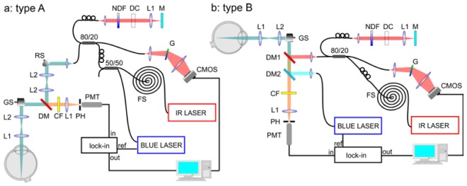
Two set-ups of the multimodal instrument for in vivo imaging of fundus autofluorescence by using lock-in detection of signal with additional modality of Fourier-domain Optical Coherence Tomography; a: device type A – blue beam is introduced into optical path of the instrument along with the near infrared beam, by 80/20 coupler; b: device type B – separate optics for pump and OCT beams, beams were combined right before the galvo scanners GS by dichroic mirrors DM1 and DM2. Detailed description is provided in a main text.
FAF-SLO mode of work
Blue beam (λ = 473 nm) from a semiconductor laser (BLUE LASER) with amplitude modulation of frequency 20 MHz is introduced into optical path of the instrument either by the first coupler input (80% of power) (device type A) or dichroic mirror DM2 (device type B). In the device type A a tiny percent of the blue beam was reflected by dichroic mirror DM into subject’s eye but it was sufficient to obtain optical power of light illuminating the cornea right below values suggested by ANSI standards. In the device type B blue exciting beam passes through the dichroic mirror DM1. In both versions of the device, the beam is reflected from mirrors of galvanometric scanners GS (Cambridge Technology, Inc.) and it is introduced into the patient’s eye by two lenses L2 and L1 of focal lengths: 50 mm and 30 mm, respectively. The beam is parallel at the cornea and it is focused on the retina by the natural optical system of subject’s eye. Diameter of the beam at the cornea is equal to 2 mm. Fluorescence radiation emitted from the fundus passes the same optical path and it is transmitted by dichroic mirror DM (device type A) or both of dichroic mirrors DM1 and DM2 (device type B). Absorption cut-off filter CF (device type A) or enhanced absorption/interference cut-off filter CF (device type B) are used for separation of laser’s wavelength. Finally, the radiation above 500 nm and below 680 nm, focused by 30 mm lens L1, reaches the photomultiplier PMT (Hamamatsu H5783-20 with preamplifier unit C11184). Pinhole PH (200 μm diameter) placed in the front of detector allows for confocal separation light incoming to detector. Signal from PMT is connected to lock-in amplifier (SRS, SR844 RF) which separates the signal of laser frequency.
OCT mode of work
Beam from Ti:Saphire laser (IR LASER) with λc = 790 nm, Δλ = 140 nm, pulse duration of 7 fs and repetition rate of 75 MHz is coupled into the 1 km spool FS of the single mode fiber which acts as a pulse stretcher. Device type A: 20 percent of the stretched IR beam is coupled in 80/20 fiber coupler which divides it between both arms of interferometer. The resonant scanner RS in the object arm is used for speckle averaging [7]. Device type B: stretched IR beam is coupled in 80/20 fiber coupler which divides it between the object (20%) and the reference (80%) arms of the interferometer. Dichroic mirror DM (device type A) and DM1 (device type B) reflects more than 99.9 percent of IR beam. The reference arm comprises: a lens L1 (30 mm) focusing light on the end mirror M, gradient neutral density filter NDF for adjustment of light power in both arms of the interferometer and glass elements DC for matching the dispersion between the reference and the object arms.
The detection of OCT signal is performed by laboratory set-up of spectrometer with transmission holographic diffraction grating G (1200 lines per mm, Wasatch Photonics) and CMOS linescan camera (Basler Sprint spL4096).
Technical parameters of both versions of our instrument are summarized in the Table 1 .
Table 1. Technical parameters of both versions of the laboratory FAF-OCT system.
| Parameter | Type A |
Type B |
||
|---|---|---|---|---|
| OCT | FAF | OCT | FAF | |
| Axial resolution [μm] | 3 | 240 | 3 | 240 |
| Transversal resolution [μm] | 12 | 10 | 12 | 8.8 |
| Sensitivity [dB] OCT | 90 | — | 90 | — |
| NEP [pW] FAF | — | 4 | — | 4 |
| Repetition frequency [kHz] | 25 | 50 | 50 | 50 |
| Irradiance [μW] | 800 | 56 | 800 | 65 |
| 500x250 image acquisition time [s] | 5 | 2.5 | 2.5 | 2.5 |
2.2. Software
Operation of the laboratory set-up was controlled by software written in LabVIEW. The software synchronizes galvo and resonant scanners and triggers the acquisition of the detected signals in both modes and it is common for both A and B versions of optical set-up.
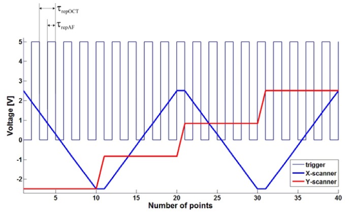
Acquisition of the signal from lock-in output is performed by analog-to-digital converter card (Alazar ATS 9462). In the type A of the device collection of FAF signal, is triggered by ascending and descending slope of TTL voltage signal called “trigger”. Trigger signal is also synchronized with voltage signal, which drives galvo scanners. In OCT mode of work the CMOS camera is triggered only by ascending slope of the TTL triggering signal. Thus for one OCT sample (one A-scan), two samples of FAF are acquired – see waveforms showed on Fig. 2 . Typical values of repetition time (time between consecutive trigger events) and acquisition time (period of time during which CMOS camera pixels are illuminated) are 40 μs and 38 μs. Repetition time in FAF mode of work is twice shorter – 20 μs. During this time period AD card collects four samples which are subsequently averaged. In version B we changed the protocol that the OCT CMOS camera and FAF analog-to-digital card are triggered simultaneously – by ascending slope of the trigger.
Fig. 2.
Voltage waveforms for X-scanner (fast), Y-scanner (slow) and trigger. For version A repetition time for AF (τrepAF) is typically equal to 20 μs and for OCT (τrepOCT) - 40 μs, both times are marked on the picture. For version B – both modalities are triggered by ascending slope of the signal.
The number of collected transverse points of image is given by the number of trigger events during one sweep of X-scanner. The number of lines on the images is determined by the number of voltage levels of Y-scanner signal during one measurement. Typical FAF image dimensions are 500x250 or 500x500 pixels, which results in total acquisition times of 2.5 s and 5 s, respectively. Exemplary voltage waveforms for both scanners are also showed in Fig. 2.
2.3. Blue beam propagation in the single mode Near Infrared single mode fiber coupler
In order to have the best possible overlap of fluorescence excitation and infrared beam in the device type A we decided to use fiber coupler to launch both beams into the device using the same collimator and fiber output. It is possible to achieve good quality of the blue beam using fiber optics elements dedicated for infrared region if a fiber coupler of specific, predetermined characteristics will be used. Typically fiber coupler consists of two optical fibers, the cores of them are placed closely on specified distance and radiation can propagate between them as an evanescent wave. Describing it more formally, we could say that there is a region where the modal structure is disturbed and field distribution must adapt to the new structure. Fiber coupler designed for 800 nm has a wider gap between cores of the fibers than the coupler designed for 473 nm, so blue beam propagating directly throughout the coupler is less affected by the core of the second fiber than the infrared beam. Consequently, the coupling efficiency of the fundamental mode for 473 nm is much smaller. Additionally, coupling efficiency for the higher order modes is bigger than for the fundamental mode and coupler plays a role of spatial mode filter (50/50 coupler in a type A of our device). As long as we use direct connections of the couplers we can preserve semi single mode operation of the infrared-designed fiber optics at 473 nm.
Some more formal explanation of the idea may be done by the beam propagation method simulations (BPM) [27]. We designed model of the fiber coupler consisting of two single mode (for 800 nm) fibers of NA = 0.12 and geometry shown in Fig. 3(a) .
Fig. 3.
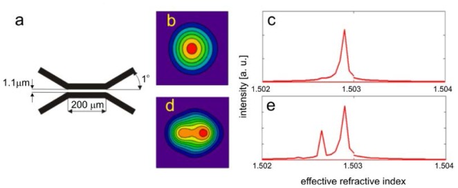
Simulation of the 473 nm beam propagation in the fiber coupler designed for 800 nm. a: geometry of considered coupler (cross-section through the center of the fiber cores), b: field distribution in direct output, c: modal content in direct output expressed as a function of in effective refractive index, d: calculated field distribution in indirect output, e: calculated modal content in indirect output.
Geometry of the simulated coupler was chosen to ensure the 50% coupling and single mode operation for 800 nm beam and 0.12 numerical aperture of the fibers. Improved BPM algorithm allows for using relatively large steps of 0.2 μm in x and y directions and very large step of 3.6 μm along propagation direction and achieving calculations accurate enough for demonstration of mode filtering. Computation grid was 100x250x400 points and transparent boundary conditions were used to avoid artificial reflections from the simulation area edges. In order to excite higher order modes we performed simulation with initial Gaussian beam with waist radius of 2 μm and 0.6 μm shifted from the fiber’s core center. As a result of the calculations we obtained field distribution in both coupler outputs. By simulating further propagation of the beams of both outputs through the 1.5 mm unbent sections of the fiber and calculating Fourier transform of the correlation function of initial field (for those 1.5 mm unbent fiber sections) and BPM result in every step along z direction we obtained modal content in both outputs of the coupler, presented in Fig. 3(b)–3(e). Simulation of light propagation in additional 1.5 mm fiber sections was performed just to calculate modal energy distribution in both coupler outputs. Correlation function of the next steps of BPM simulation and beam of interest, taken into simulation as an initial conditions, periodically changes along propagation direction. There are different periods of this function for different propagation constants corresponding to different modes and Fourier transform of correlation function reveals peaks at positions corresponding to propagation constants of the modes (simply related to effective refractive indexes of the modes). Height of these peaks is proportional to electric field intensity of the modes in initial beam.
Presented results of calculations show that in the direct output of the coupler only negligible content of the higher order modes is present. To verify the calculation we measured the shape of the beam after the first collimator in the object arm of our device and found no signs of multimode operation, what is in good agreement with the simulations. The same calculations performed for 800 nm resulted in 50% splitting ratio and single mode operation of the coupler. A part of relatively short fiber, which connects coupler and device input was fixed possibly straight to avoid cross-talk between modes. However, in practice as long as there are no defects in the fibers or bends of small radius, modal energy distribution is not disturbed in the fiber sections of length of at least 1m.
2.4. System sensitivity in FAF mode of work
In order to obtain objective and reliable indicator of sensitivity of the system the procedure described below was implemented. It was performed for both device types and gave unchanged results.
To obtain a point source of well-defined power placed in the detection plane of our system we used additional lens (f = 25.4 mm) and a mirror at the end of the object arm. Power of the blue laser was additionally attenuated to the level of a few tenths of nanowatts by neutral density filters and the cut-off filter (and dichroic mirror DM2 – in a case of device type B) from the detection path was removed. The level of voltage increment at the lock-in output versus optical power of such defined point source is presented in the Fig. 4 . It can be seen that the dependence is linear.
Fig. 4.
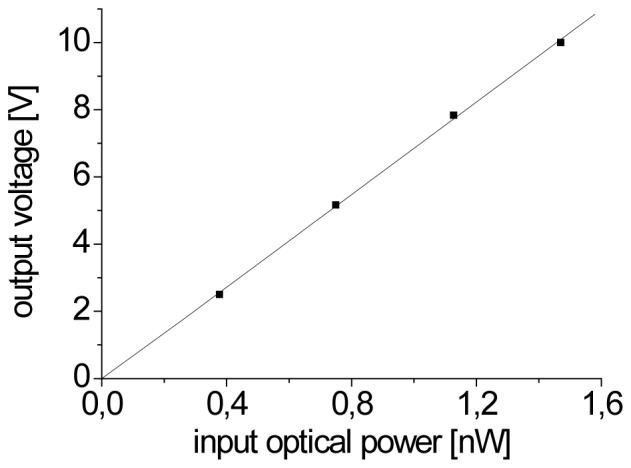
The relative increase in the output voltage of lock-in amplifier versus optical power of point source placed in the detection plane of the system.
The noise level of voltage on the lock-in output was 0.028 mV and, in agreement with slope of the line from Fig. 4, it corresponds to noise equivalent power (NEP) of 4 pW. Basing on the determined NEP value and taking into account average power of blue laser beam applied during eye measurement (Papplied = 56 μW and Papplied = 65 μW for type A and type B of the device, respectively) we can say that boundary value of quantum yield of the fluorescence of the object that we can detect is 7·10−8 and 6·10−8.
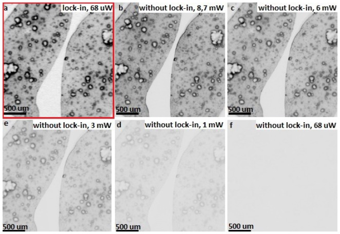
For quantifying influence of using lock-in for the sensitivity of our system we use a phantom sample stained with pigment (cresyl violet), which has an emission in the detection window of our system. The sample was imaged with 25.4 mm focusing lens with and without using lock-in amplifier. For lock-in assisted measurement the beam power applied for the sample was 68 μW and the modulation frequency was 20 Hz - resulted image is presented in the Fig. 5(a) . Subsequently the sample was imaged with non-modulated laser beam and the signal from PMT amplifier output was directly connected to A/D card – results are presented in the Fig. 5(b)-5(f). One can see that to obtain the fluorescence image with similar contrast to presented in Fig. 5(a) we had to increase beam power to the level of 8.7 mW. Furthermore, there is nothing but noise at the image obtained with beam power of 68 μW with no using lock-in – Fig. 5(f). The dynamic range of 16 bit is the same for all images.
Fig. 5.
Images of the phantom pigment sample (stained with cresyl violet) acquired with (a) and without (b-f) lock-in detection.
2.5. Optical resolution in FAF images
For quantifying optical resolution of our system we used USAF 1951 target in the object arm configuration described above. Different ranges of voltage applied to scanners lead to different dimensions of scanned region of the retina. The same number of points in each acquired image causes increase of the sampling density on the retina and, in consequence, resolution is better in images gathered from smaller regions. The best obtained PSF values are below 10 μm.
In our set-up the acquisition speed is limited mainly by the bandwidth of SRS SR844 lock-in amplifier. Even if we use it in so-called “No filter” mode, the update rate is between 10 μs and 20 μs. If the frequency of generating consecutive trigger events is sufficiently low, we obtain images with resolution limited only by optical parameters of our system. With increasing acquisition frequency lock-in constant can reach the repetition time. In such case we observe streaking of the FAF image along fast X-axis – Fig. 6 .
Fig. 6.

Streaking effect along X-axis observed on USAF 1951 for images with increasing repetition frequency.
In the Fig. 7 we plotted point spread function PSF of our system determined on the basis of USAF 1951 target placed in the detection plane (configuration of object arm was the same as described in chapter 2.4 but we placed USAF target instead of mirror). It can be seen that the increase in the scanning speed results in linear deterioration of PSF in the direction of the fast axis scan. The effect has no influence on the slow Y-axis scan.
Fig. 7.
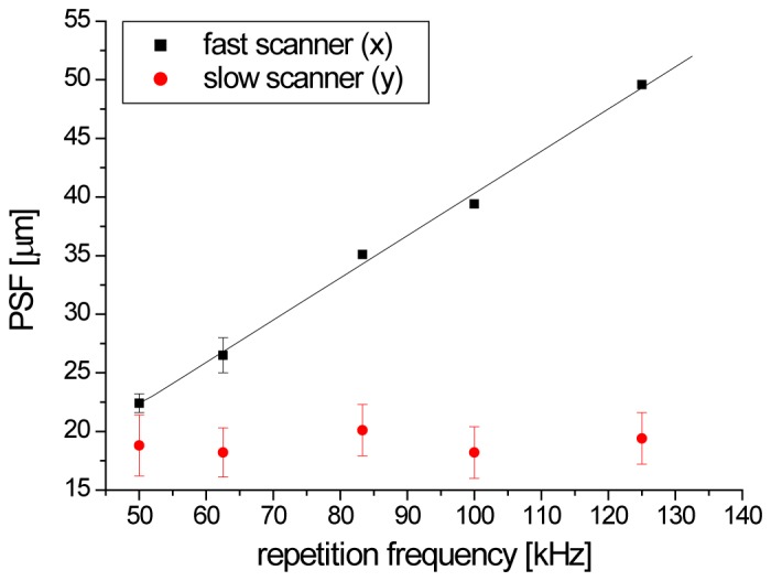
Deterioration of PSF along X-axis (fast scanner) with ascending repetition frequency.
2.7. Compliance with safety standards and declaration of Helsinki
All the test have been conducted in compliance with ANSI recommended exposure limits. The optical powers of the beams incident at the cornea were 56 and 65 μW for the 473 nm laser beam and 800 μW for the infrared beam from Ti:Saphire laser. The study was approved by the Ethics Committee of the Collegium Medicum in Bydgoszcz, Nicolaus Copernicus University in Torun, Poland. Examinations were conducted after written informed consent was obtained.
3. Results
FAF single frame images of healthy 32 years old volunteer’s fundus are presented in Fig. 8 . We observe the spatial distribution of intensity of fluorescence (Fig. 9(a) ) similar to that reported in the literature [28] with the central minimum of fluorescence signal in the fovea caused by absorption of melanin and the macular pigment. The most intensive region of autofluorescence signal is located at the superior-temporal side of the fundus [5]. Retinal blood vessels cast shadows obstructing RPE fluorescence. Region of optics disc is hypofluorescent due to absence of RPE in this region. Images 8b-g were taken as separate measurements from smaller regions placed in the superior side of the fundus. There is small granulation of fluorescence intensity of the size of 20-40 μm visible on these images. Similar structures are typical for FAF images [5, 29]. It is not clear if that irregularities results from the morphology of the RPE or from propagation of emitted fluorescence through other tissues of the eye. Lately reported fluorescence images of the retina by means of the adaptive optics SLO suggest that these structures are likely due to non-uniform subretinal pigmentation and/or choroidal vasculature [30, 31]. In order to exclude impact of speckles created by excitation with blue laser beam the measurements were repeated in the same region showing identical distribution of fluorescent granules.
Fig. 8.
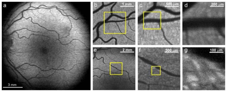
a: Autofluorescence images of the fundus of the left eye of 32 years old healthy volunteer; b-d: images taken from smaller regions from superior part of the fundus; e-g: images taken from the region central superior periphery of the macula. All images were obtained with device type A, average power of the exciting beam was set to 56 μW. All presented images are single frames, without averaging.
Fig. 9.
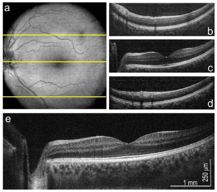
OCT imaging mode of FAF/OCT multimodal instrument, the left eye of 32 years old healthy volunteer; a: en face projection of fundus 500x500 pixels; b-d: B-scans originating from regions of fundus indicated with yellow lines; e: high resolution (2048 A-scans) B-scan from the center of the fovea. The OCT data were purchased by version A of described system.
Described instrument has a complete functionality of OCT system with sensitivity of 90 dB. Structures of the eye presented in Fig. 9 were imaged by using OCT beam of 800 μW. En face image of dimensions of 500x500 pixel is presented in the Fig. 9(a). Anatomical structures are consistent with ones visible in FAF images. Dark spot present at upper temporal in this picture is caused probably by shadow of non-pathological opacity in vitreous. B-scans originating from selected regions of fundus (indicated by yellow lines) are presented in Fig. 9(b)-9(d). In order to verify the functionality of OCT mode of work, we measure also high resolved B-scan consisted from 2048 A-scans at the center of the fovea – Fig. 9(e). The result is comparable to reported previously high resolution (3 μm) OCT cross-sectional images [6].
Experimental verification of high sensitivity of our FAF system in version A configuration was performed by decreasing power of exciting beam from 50 μW to 10 μW and, further, even to 4,5 μW – resulting images are presented in Fig. 10 . Even for such low excitation powers, position of optic nerve and macula and some vessel patterns are recognizable on FAF images.
Fig. 10.
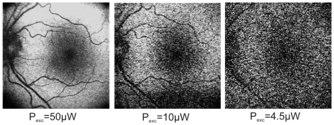
FAF images of fundus of the left eye of 32 years old healthy volunteer for small powers of exciting beam for device type A. All presented images are single frames, without averaging.
In vivo FAF measurements as other fundus imaging techniques are sensitive to small aberrations of natural optical system of the human eye since the cornea, lens, vitreous with its natural imperfections are the crucial elements of imaging device. Fluorescence signal, originating from the bottom part of the retina, has to be directed through all these elements as well as through the pupil. Since our work is just a proof of concept we have not dilated the pupil in our experiments. In contrast to near infrared imaging blue laser beam is visible and the pupil constricts causing a limitation of the transverse field of view.
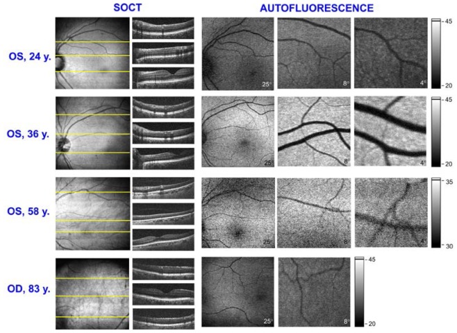
We tested a real applicability of the device type B performing measurements of 8 volunteers from different age groups. The amount of lipofuscin deposited in RPE layer increases with age [28] and so we could expect that it will be represented in the intensity of FAF images. Results of these measurements are presented in Fig. 11 . The most pronounced difference is visible between FAF images of 24 years patient and 36 years old one.
Fig. 11.
FAF and OCT images obtained for volunteers of different age groups with device type B. Beam powers were set to 800 μW for OCT and 65 μW for FAF. All presented FAF images are single frames, without averaging. FAF images for 24y., 36y. and 83 y. subjects are displayed in the same grayscale.
At the top line of Fig. 11, FAF and OCT images of the left eye of youngest examined subject, 24 years old woman, are presented. We obtained FAF images of different regions of the retina and corresponding OCT en-face projection and B-scans of quality comparable to images presented in Fig. 9 and 10. In the second line there are results obtained for 36 years old woman and, as we expected, the FAF signal from her fundus was higher than for younger one. In this case the autofluorescence efficiency and high quality of the eye optics seems to be optimal for imaging. FAF and OCT images of older subjects have slightly worse quality. In this case increased autofluorescence is compromised by the aging of anterior segment of the eye. The 58 years old man has a high myopia and a proper fixation of his eye was significantly impeded. It resulted in lowering fluorescence signal and impaired contrast on images. In the bottom line of Fig. 11 there are images obtained for the oldest subject: 83 years old man, six years after cataract surgery. This case demonstrates that it is possible to obtain FAF images of the fundus of the eye with intraocular lens. Probably it was helpful that problems with fixation and focusing were compensated by high autofluorescence from larger amount of lipofuscin deposits.
4. Conclusions
In this paper we demonstrated a new multimodal device for retinal imaging, which combines autofluorescence (FAF) and Fourier domain Optical Coherence Tomography (OCT).
The sensitivity of FAF system was improved by using lock-in detection enabling FAF imaging of the human fundus with 50-70 μW average power of exciting beam which is three to four times lower than for previously reported systems [4]. Our system allows for obtaining high resolution FAF images without additional averaging (single frames).
Noise equivalent power (NEP) for the device working in AF mode is equal to 4 pW. Resulting boundary value of quantum yield of the fluorescence of the object that can be detected is 6·10−8.
Degradation of transverse resolution due to rate of the lock-in amplifier is significant for repetition frequency higher than 50 kHz.
We tested the functionality of presented device for subjects from different age groups (from 24 to 83 years old). Demonstrated FAF and OCT images of eyes with different ages show that our instrument is sensitive enough to provide acceptable FAF images. This instrumentation can be further ergonomized and optimized to work in clinical conditions.
Acknowledgements
Authors acknowledge all members of Optical Biomedical Imaging Group and Medical Physics Group for their kind assistance. We would like to give our special thanks to Karol Karnowski and Marcin Sylwestrzak for their helpful advances and support in LabVIEW programming. This work was supported by the TEAM project financed by European Union within the frames of Innovative Economy coordinated by Foundation for Polish Science.
References and links
- 1.Webb R. H., Hughes G. W., Delori F. C., “Confocal Scanning Laser Ophthalmoscope,” Appl. Opt. 26(8), 1492–1499 (1987). 10.1364/AO.26.001492 [DOI] [PubMed] [Google Scholar]
- 2.von Rückmann A., Fitzke F. W., Bird A. C., “Distribution of Fundus Autofluorescence with a Scanning Laser Ophthalmoscope,” Br. J. Ophthalmol. 79(5), 407–412 (1995). 10.1136/bjo.79.5.407 [DOI] [PMC free article] [PubMed] [Google Scholar]
- 3.von Rückmann A., Fitzke F. W., Bird A. C., “Fundus autofluorescence in age-related macular disease imaged with a laser scanning ophthalmoscope,” Invest. Ophthalmol. Vis. Sci. 38(2), 478–486 (1997). [PubMed] [Google Scholar]
- 4.Bellmann C., Rubin G. S., Kabanarou S. A., Bird A. C., Fitzke F. W., “Fundus autofluorescence imaging compared with different confocal scanning laser ophthalmoscopes,” Br. J. Ophthalmol. 87(11), 1381–1386 (2003). 10.1136/bjo.87.11.1381 [DOI] [PMC free article] [PubMed] [Google Scholar]
- 5.S. Schmitz-Valckenberg and F. Fitzke, “Imaging Techniques of Fundus Autofluorescence,” in Fundus autofluorescence, N. Lois and J. V. Forrester, eds. (Wolters Kluwer, Lippincott Williams & Wilkins, 2009). [Google Scholar]
- 6.Wojtkowski M., “High-speed optical coherence tomography: basics and applications,” Appl. Opt. 49(16), D30–D61 (2010). 10.1364/AO.49.000D30 [DOI] [PubMed] [Google Scholar]
- 7.Szkulmowski M., Gorczynska I., Szlag D., Sylwestrzak M., Kowalczyk A., Wojtkowski M., “Efficient reduction of speckle noise in Optical Coherence Tomography,” Opt. Express 20(2), 1337–1359 (2012). 10.1364/OE.20.001337 [DOI] [PubMed] [Google Scholar]
- 8.Delori F. C., “Spectrophotometer for Noninvasive Measurement of Intrinsic Fluorescence and Reflectance of the Ocular Fundus,” Appl. Opt. 33(31), 7439–7452 (1994). 10.1364/AO.33.007439 [DOI] [PubMed] [Google Scholar]
- 9.Delori F. C., Dorey C. K., Staurenghi G., Arend O., Goger D. G., Weiter J. J., “In Vivo Fluorescence of the Ocular Fundus Exhibits Retinal Pigment Epithelium Lipofuscin Characteristics,” Invest. Ophthalmol. Vis. Sci. 36(3), 718–729 (1995). [PubMed] [Google Scholar]
- 10.S. S. Seehafer and D. A. Pearce, “Lipofuscin: The “Wear and Tear” Pigment,” in Fundus Autofluorescence, N. Lois and J. V. Forrester, eds. (Wolters Kluwer, Lippincott Williams & Wilkins, 2009). [Google Scholar]
- 11.N. Lois and J. V. Forrester, eds., Fundus Autofluorescence (Wolters Kluwer, Lippincott Williams & Wilkins, 2009). [Google Scholar]
- 12.Strauss O., “The retinal pigment epithelium in visual function,” Physiol. Rev. 85(3), 845–881 (2005). 10.1152/physrev.00021.2004 [DOI] [PubMed] [Google Scholar]
- 13.M. Boulton, “Lipofuscin of the Retinal Pigment Epithelium,” in Fundus Autofluorescence, N. Lois and J. V. Forrester, eds. (Wolters Kluwer, Lippincott Williams & Wilkins, 2009). [Google Scholar]
- 14.Sparrow J. R., Boulton M., “RPE lipofuscin and its role in retinal pathobiology,” Exp. Eye Res. 80(5), 595–606 (2005). 10.1016/j.exer.2005.01.007 [DOI] [PubMed] [Google Scholar]
- 15.Eldred G. E., Lasky M. R., “Retinal Age Pigments Generated by Self-Assembling Lysosomotropic Detergents,” Nature 361(6414), 724–726 (1993). 10.1038/361724a0 [DOI] [PubMed] [Google Scholar]
- 16.Rózanowska M., Sarna T., “Light-induced damage to the retina: Role of rhodopsin chromophore revisited,” Photochem. Photobiol. 81(6), 1305–1330 (2005). 10.1562/2004-11-13-IR-371 [DOI] [PubMed] [Google Scholar]
- 17.Haralampus-Grynaviski N. M., Lamb L. E., Clancy C. M. R., Skumatz C., Burke J. M., Sarna T., Simon J. D., “Spectroscopic and morphological studies of human retinal lipofuscin granules,” Proc. Natl. Acad. Sci. U.S.A. 100(6), 3179–3184 (2003). 10.1073/pnas.0630280100 [DOI] [PMC free article] [PubMed] [Google Scholar]
- 18.Schweitzer D., Kolb A., Hammer M., “Autofluorescence lifetime measurements in images of the human ocular fundus,” Diagn. Opt. Spectros. Biomed. 2, 29–39 (2001). 10.1117/12.447153 [DOI] [Google Scholar]
- 19.Schweitzer D., Hammer M., Schweitzer F., Anders R., Doebbecke T., Schenke S., Gaillard E. R., Gaillard E. R., “In vivo measurement of time-resolved autofluorescence at the human fundus,” J. Biomed. Opt. 9(6), 1214–1222 (2004). 10.1117/1.1806833 [DOI] [PubMed] [Google Scholar]
- 20.Schweitzer D., Schenke S., Hammer M., Schweitzer F., Jentsch S., Birckner E., Becker W., Bergmann A., “Towards metabolic mapping of the human retina,” Microsc. Res. Tech. 70(5), 410–419 (2007). 10.1002/jemt.20427 [DOI] [PubMed] [Google Scholar]
- 21.Schweitzer D., Gaillard E. R., Dillon J., Mullins R. F., Russell S., Hoffmann B., Peters S., Hammer M., Biskup C., “Time-Resolved Autofluorescence Imaging of Human Donor Retina Tissue from Donors with Significant Extramacular Drusen,” Invest. Ophthalmol. Vis. Sci. 53(7), 3376–3386 (2012). 10.1167/iovs.11-8970 [DOI] [PMC free article] [PubMed] [Google Scholar]
- 22.Blue Laser Autofluorescence: the new experience” (a webpage of Heidelberg Engineering, 2013), retrieved http://bluepeakexperience.com/us
- 23.Potma E. O., Evans C. L., Xie X. S., “Heterodyne coherent anti-Stokes Raman scattering (CARS) imaging,” Opt. Lett. 31(2), 241–243 (2006). 10.1364/OL.31.000241 [DOI] [PubMed] [Google Scholar]
- 24.Freudiger C. W., Min W., Saar B. G., Lu S., Holtom G. R., He C., Tsai J. C., Kang J. X., Xie X. S., “Label-Free Biomedical Imaging with High Sensitivity by Stimulated Raman Scattering Microscopy,” Science 322(5909), 1857–1861 (2008). 10.1126/science.1165758 [DOI] [PMC free article] [PubMed] [Google Scholar]
- 25.Applegate B. E., Izatt J. A., “Molecular imaging of endogenous and exogenous chromophores using ground state recovery pump-probe optical coherence tomography,” Opt. Express 14(20), 9142–9155 (2006). 10.1364/OE.14.009142 [DOI] [PubMed] [Google Scholar]
- 26.Slipchenko M. N., Oglesbee R. A., Zhang D. L., Wu W., Cheng J. X., “Heterodyne detected nonlinear optical imaging in a lock-in free manner,” J Biophotonics 5(10), 801–807 (2012). 10.1002/jbio.201200005 [DOI] [PubMed] [Google Scholar]
- 27.Ma C. B., Van Keuren E., “A simple three dimensional wide-angle beam propagation method,” Opt. Express 14(11), 4668–4674 (2006). 10.1364/OE.14.004668 [DOI] [PubMed] [Google Scholar]
- 28.Delori F. C., Goger D. G., Dorey C. K., “Age-related accumulation and spatial distribution of lipofuscin in RPE of normal subjects,” Invest. Ophthalmol. Vis. Sci. 42(8), 1855–1866 (2001). [PubMed] [Google Scholar]
- 29.Bindewald A., Bird A. C., Dandekar S. S., Dolar-Szczasny J., Dreyhaupt J., Fitzke F. W., Einbock W., Holz F. G., Jorzik J. J., Keilhauer C., Lois N., Mlynski J., Pauleikhoff D., Staurenghi G., Wolf S., “Classification of fundus autofluorescence patterns in early age-related macular disease,” Invest. Ophthalmol. Vis. Sci. 46(9), 3309–3314 (2005). 10.1167/iovs.04-0430 [DOI] [PubMed] [Google Scholar]
- 30.A. Dubra, D. H. Scoles, and Y. N. Sulai, “In vivo Imaging of the Human Retinal Pigment Epithelium Cell Mosaic using Short-wavelength Autofluorescence and achromatizing lenses., ” in ARVO Annual Meeting, (Seattle, WA, USA, 2013). [Google Scholar]
- 31.D. H. Scoles, Y. N. Sulai, and A. Dubra, “In vivo Imaging of the retinal pigment epithelium using dark-field SLO,” in ARVO-ISIE Imaging Conference, 2013) [DOI] [PMC free article] [PubMed] [Google Scholar]


