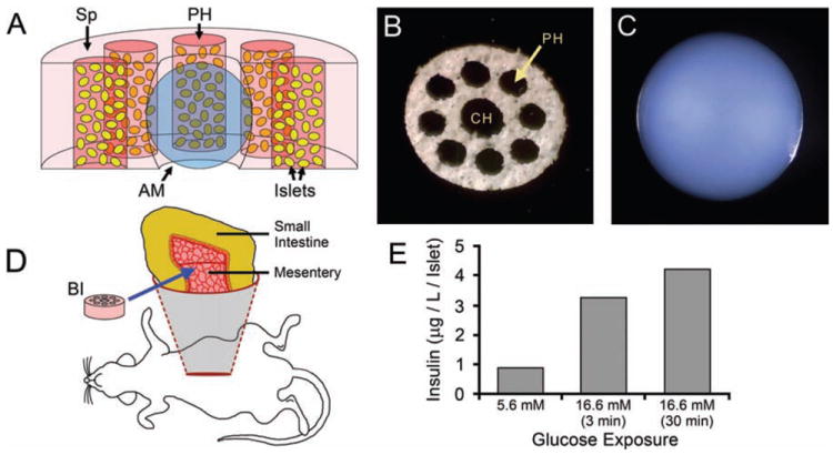
Figure 1.

BI fabrication and implantation. (A) Cut-away diagram of the bioengineered islet (BI), with the components shown to scale. A disk-shaped polyvinyl alcohol (PVA) sponge (Sp) scaffold provides mechanical support. An alginate macrosphere (AM) (blue) occupies the central hole of the sponge. Eight peripheral holes (PH) in the sponge (5 appear in this cut-away) contain islets (yellow) suspended in a type 1 collagen hydrogel (reddish-pink). The collagen hydrogel also infuses the sponge (light pink). For clarity, the pores of the sponge are not depicted. (B) A PVA sponge scaffold oriented to show the central hole (CH) and peripheral holes (PH). The scaffold is 6 mm in diameter. (C) An alginate macrosphere of 2 mm diameter. (D) Diagram illustrating placement of the BI (pink disk) on the mesentery supporting a loop of small intestine. (E) Islets within freshly-made BIs (500 islets per BI) increased their production of insulin in vitro following 3- or 30-min exposures to elevated (16.6 mM) glucose, as compared to “resting” levels of insulin produced in the presence of low (5.6 mM) glucose.
