Abstract
A molecular proton reduction catalyst [FeFe](dcbdt)(CO)6 (1, dcbdt = 1,4-dicarboxylbenzene-2,3-dithiolate) with structural similarities to [FeFe]-hydrogenase active sites has been incorporated into a highly robust Zr(IV)-based metal–organic framework (MOF) by postsynthetic exchange (PSE). The PSE protocol is crucial as direct solvothermal synthesis fails to produce the functionalized MOF. The molecular integrity of the organometallic site within the MOF is demonstrated by a variety of techniques, including X-ray absorption spectroscopy. In conjunction with [Ru(bpy)3]2+ as a photosensitizer and ascorbate as an electron donor, MOF-[FeFe](dcbdt)(CO)6 catalyzes photochemical hydrogen evolution in water at pH 5. The immobilized catalyst shows substantially improved initial rates and overall hydrogen production when compared to a reference system of complex 1 in solution. Improved catalytic performance is ascribed to structural stabilization of the complex when incorporated in the MOF as well as the protection of reduced catalysts 1– and 12– from undesirable charge recombination with oxidized ascorbate.
Introduction
The direct conversion of solar energy to a chemical fuel is an essential part of future sustainable energy systems that are independent of fossil reserves.1,2 Hydrogen is an environmentally benign energy carrier of high-energy density and can be produced by photocatalytic water reduction.3 Platinum and other noble metals can serve as heterogeneous hydrogen evolution catalysts; however, their limited earth abundance and cost precludes further development and/or large-scale applications.4,5 On the other hand, organometallic compounds are attractive catalysts for this transformation considering the variety of complexes that can be prepared, the synthetic ease with which electronic properties (and hence catalyst activity) can be modulated, and the ability to study their mechanisms in detail. In nature, hydrogenase enzymes, especially those containing Fe2 active sites, efficiently catalyze proton reduction to molecular dihydrogen.6,7 Models of the [FeFe]-hydrogenases can act as biomimetic hydrogen evolution catalysts,8 although they often suffer from limited stability, especially when catalysis is driven photochemically in conjunction with photosensitizers.9 The necessity of an external matrix to stabilize the catalyst is thus evident.
Metal–organic frameworks (MOFs), also referred to as porous coordination polymers, have emerged as an intriguing class of microporous crystalline materials due to their intrinsic topology and porosity10 and have been studied for a range of applications in gas storage/separation,11,12 chemical sensing,13 drug delivery,14 and catalysis.15 Unlike other porous materials such as zeolites, the organic ligand component of MOFs allows for functionalization of internal channels and/or cavities either through direct solvothermal synthesis16 or by postsynthetic modification reactions that include the metathesis of metal ions and organic linkers under relatively mild conditions.17−26 Hupp, Cohen, and others have reported on this postsynthetic exchange (PSE) phenomenon (also termed solvent-assisted linker exchange, SALE), including in highly robust MOFs, such as the Materials of the Institute Lavoisier, Zeolitic Imidaozolate Framework, and University of Oslo (UiO) materials.27−30 All of these materials are considered to be “inert” with exceptionally high thermal and chemical stability, and can provide a robust platform for the incorporation of potentially labile molecular catalysts.
Incorporation of catalytic sites into MOFs has resulted in heterogeneous catalysts that promote a wide range of organic reactions. The heterogeneous nature of MOF catalysts allows for their easy separation, reusability, and enhanced stability.31,32 In the context of light-to-fuel conversion schemes, homogeneous photosensitizers such as Ir polypyridine complexes33 and porphyrins34 have been incorporated in MOFs and were shown to drive photochemical hydrogen production catalyzed by Pt nanoparticles.35 Organometallic Ir and Re catalysts have been incorporated as the ligand linker part of the MOF and were shown to catalyze CeIV-promoted water oxidation36 and photochemical CO2 reduction, respectively.37
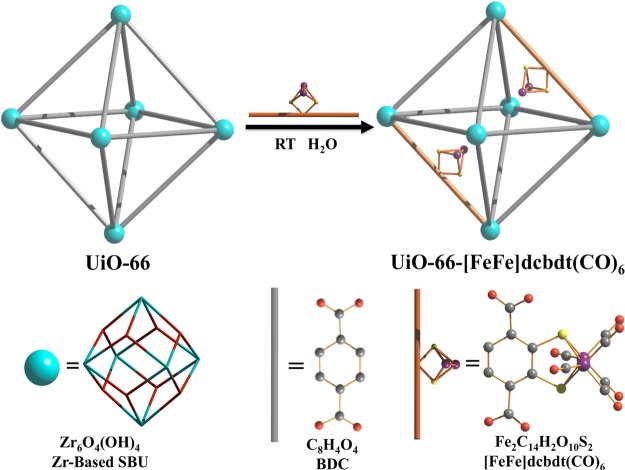
Although excellent proof-of-concept studies, in both cases, resource-limited precious metal catalytic sites were used. Moreover, the scope of these reports is somewhat limited, as the solvothermal procedures that were used for the synthesis of the MOFs require organometallic units that are thermally robust. Herein, we describe the incorporation of an organometallic Fe2 complex that bears structural resemblance to the active site of [FeFe] H2ases into a MOF. [FeFe](bdt)(CO)6 (2) (bdt = benzenedithiolate) has previously been shown to be an effective proton reduction catalyst in electro- and photochemical schemes.38,39 Decoration of complex 2 at the bdt ligand with two carboxylates results in complex 1 which can be introduced into MOFs by PSE of 1,4-benzenedicarboxylate (BDC) ligands, which is a common ligand linker in many MOFs (Figure 1). PSE thus allowed for the introduction of a thermally unstable [FeFe](bdt)(CO)6 moiety into the thermally stable Zr(IV)-based UiO-66 MOF (Figure 2). X-ray absorption spectroscopy (XAS) was used to confirm the coordination environment of the Fe2 site in the MOF. Importantly, UiO-66-[FeFe](dcbdt)(CO)6 was found to be a highly active hydrogen production catalyst in photochemical arrays with [Ru(bpy)3]2+ as a photosensitizer and ascorbate as an electron donor. The catalytic performance of the MOF exceeds that of an analogous homogeneous reference system.
Figure 1.
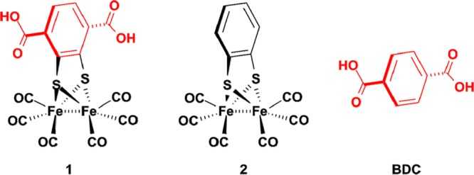
[FeFe] hydrogenase active site model complexes [FeFe](dcbdt)(CO)61 and [FeFe](bdt)(CO)62 and the BDC ligand.
Figure 2.
Schematic representation of PSE of 1 into UiO-66.
Results and Discussion
2,3-Dimercaptoterephthalic acid was prepared from benzene-1,2-dithiole via lithiation and carboxylation40,41 and directly converted to complex 1 ([FeFe](dcbdt)(CO)6, dcbdt =1,4-dicarboxylbenzene-2,3-ditiolate) by combining the ligand with Fe3(CO)12 in THF. Single crystal X-ray analysis of complex 1 shows the usual distorted octahedral coordination sphere around the Fe ions, with the dcbdt ligand perpendicular to the Fe–Fe bond vector (see also ESI).
The UiO-66 framework, consisting of Zr(IV)-based secondary building units (SBUs) and BDC ligand (Zr6O4(OH)4(BDC)6), was chosen for the incorporation of complex 1 because of its exceptionally high structural stability with respect to water and weak acids. Highly crystalline UiO-66 was synthesized under solvothermal conditions using ZrCl4, BDC, and benzoic acid (as a crystal growth modulator) in DMF for 24 h, followed by washing with MeOH and activation under vacuum. Field-emission scanning electron microscopy (FE-SEM) shows an octahedral morphology of the resultant UiO-66 crystals with a particle size ranging from ∼200 to 500 nm (Figure 3).
Figure 3.
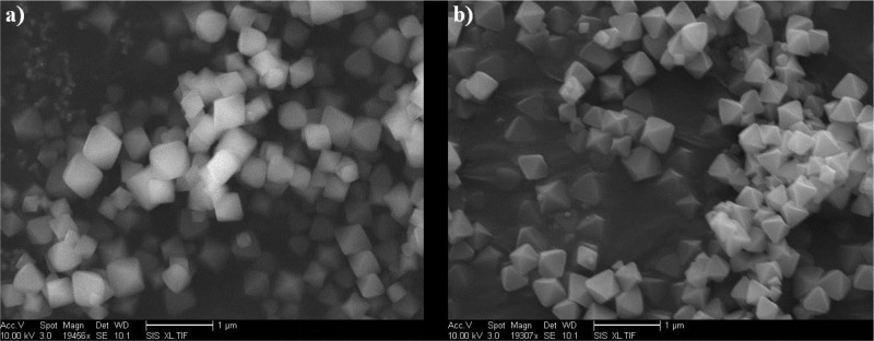
FE-SEM image of (a) UiO-66 and (b) UiO-66-[FeFe](dcbdt)(CO)6. Scale bar is 1 μm.
Attempts to directly include 1 during solvothermal synthesis (>50 °C) resulted in decomposition of the cluster, presumably due to the labile bonds between the Fe centers and the highly electron-deficient dcbdt ligand. Taking advantage of the structural homology of the BDC and dcbdt ligands in complex 1 (Figure 1), we employed PSE as a mild functionalization approach to introduce complex 1 into UiO-66 (Figure 2). Optimization of the PSE conditions revealed that the use of deoxygenated, ultrapure water (room temperature for 24 h) produced the best exchange results. Organic solvents, including MeOH, DMF, and CHCl3, gave lower incorporation, consistent with previous observations on the solvent dependence of PSE.27 As expected from the attempted solvothermal syntheses, PSE at elevated temperatures (>50 °C) gave results that also suggested partial decomposition of 1. Interestingly, it was found that PSE was facilitated by using a highly microcrystalline form of UiO-66 that was synthesized in the presence of a benzoic acid modulator. In contrast, conventionally synthesized UiO-66 (without modulator) resulted in a less crystalline material and a less efficient exchange process.
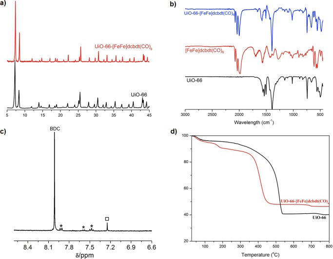
The linker-exchanged material, UiO-66-[FeFe](dcbdt)(CO)6, was isolated as an orange microcrystalline powder after washing thoroughly with fresh MeOH and activation under vacuum. Activated UiO-66-[FeFe](dcbdt)(CO)6 exhibited a Brunauer–Emmett–Teller (BET) surface area of 1357 ± 25 g/cm–1, measured with nitrogen at 77 K. This value is close to the BET surface area of pristine UiO-66 (1475 ± 89 g/cm–1), suggesting a true PSE process between 1 and the framework, and not simple trapping of the iron complex in the MOF pores (which would be expected to produce a much lower surface area). N2 absorption/desorption isotherms of UiO-66 and UiO-66-[FeFe]dcbdt(CO)6 do indicate a modest decrease in pore size distribution (Figure S1). UiO-66 is known to possess two pore types, tetrahedral and octahedral cages, with pore widths of ∼8 and ∼11 Å, respectively (Figure S2).43,44 Pristine UiO-66 gave a median pore width of ∼11.8 Å, while after incorporation of 1, a reduction in the median pore width to ∼10.9 Å was observed, consistent with incorporation of the [Fe2S2] functionality in UiO-66-[FeFe]dcbdt(CO)6. Powder X-ray diffraction (PXRD) patterns before and after PSE confirmed the retention of the crystalline UiO-66 framework (Figure 4a). FE-SEM showed that UiO-66-[FeFe](dcbdt)(CO)6 possesses a nearly identical particle size and octahedral particle morphology compared to UiO-66, again indicative of a PSE mechanism (Figure 3).
Figure 4.
(a) PXRD of UiO-66 and UiO-66-[FeFe](dcbdt)(CO)6. (b) FTIR of UiO-66, [FeFe](dcbdt)(CO)6, and UiO-66-[FeFe](dcbdt)(CO)6. (c) 1H NMR spectrum of HF/d6-DMSO digested UiO-66-[FeFe](dcbdt)(CO)6. Asterisks indicate remaining benzoic acid (modulator) and the black square indicates dcbdt. (d) TGA of UiO-66 and UiO-66-[FeFe](dcbdt)(CO)6.
The degree of PSE was characterized by energy-dispersed X-ray spectroscopy (EDX), elemental analysis (EA), thermogravimetric analysis (TGA), and proton nuclear magnetic resonance spectroscopy (1H NMR). The ratio of heavy elements in UiO-66-[FeFe](dcbdt)(CO)6 was determined to be 3.52:1:1.01 (Zr:Fe:S, normalized to Fe) via EDX, which suggests that ∼14% of BDC in UiO-66 was exchanged for [FeFe](dcbdt)(CO)6 (Figure S3). The expected 1:1 Fe/S ratio determined by EDX also further supports that the cluster is intact within the MOF. Treatment of UiO-66-[FeFe](dcbdt)(CO)6 with dilute HF/d6-DMSO was used to digest the MOF but also decomposed [FeFe](dcbdt)(CO)6 to dcbdt. Integration of the proton resonances for BDC and dcbdt in the 1H NMR confirmed the degree of PSE at ∼14% (Figure 4), giving an overall formula for UiO-66-[FeFe](dcbdt)(CO)6 as Zr6O4(OH)4(BDC)5.1([FeFe](dcbdt)(CO)6)0.9·2CH3OH. Based on this given formula, C/H/N/S elemental analysis also confirmed the degree of functionalization [C(%): 32.75 (obs), 32.80 (calcd); H(%): 1.75 (obs), 1.68 (calcd); N(%): 0.00 (obs), 0.00 (calcd); S(%): 2.97 (obs), 2.84 (calcd)]. Unlike pristine UiO-66, which displays only one major decomposition step at ∼400 °C, the TGA trace of UiO-66-[FeFe](dcbdt)(CO)6 exhibits two decomposition steps at ∼80–200 and ∼350–400 °C, respectively (Figure 4). The first mass loss is likely due to partial thermal liberation of the carbonyl ligands attached to Fe centers (obs: 7%; calcd: 7.2%). Both BDC and [FeFe](dcbdt)(CO)6 start to decompose at ∼350 °C, leading to a combination of ZrO2 and Fe2O phases (obs: 46.3%; calcd: 43.6%, percent weight residual mass).
To confirm that compound 1 was being incorporated into the framework lattice to give UiO-66-[FeFe]dcbdt(CO)6, additional experiments were performed to exclude the possibility that compound 1 was merely trapped in the pores of the MOF. In one experiment, PSE between UiO-66 and compound 2 was performed. Compound 2 (Figure 1) contains the same cluster core but lacks the coordinating carboxylate ligands required for MOF formation and hence PSE. Incubation of UiO-66 with compound 2 showed no evidence of substantial incorporation into the MOF as shown by a lack of color change (Figure S4) and a low iron content in the EDX analysis (Figure S5). In a second experiment, PSE between UiO-66 and 1 was performed in D2O, and the presence of BDC was observed in the reaction solution, as determined by 1H NMR (Figure S6), indicative of displacement of BDC by 1. Importantly, UiO-66 in D2O in the absence of 1 does not show release of free BDC into solution. These NMR observations are also indicative of a ligand metathesis process and argue against simple inclusion of 1 into the pores of the MOF. Finally, as stated above, performing PSE between UiO-66 and 1 in other solvents (MeOH, DMF, and CHCl3) was not efficient, achieving negligible incorporation (<2%), consistent with the known solvent dependence of PSE processes.27 If complex 1 was only being included into UiO-66 via sorption into the pores, then inclusion would not be expected to be strongly solvent dependent. Taken together, these experiments provide strong evidence, consistent with reported PSE studies, that the iron cluster is becoming part of the UiO-66 framework via a ligand PSE process and that the data do not support simple inclusion of the cluster into the pores of the MOF.
In order to further demonstrate the incorporation of the intact Fe2S2 dinuclear cluster into the MOF, we employed Fourier-transformed infrared spectroscopy (FTIR) and diffuse reflectance UV–vis spectroscopy. FTIR of UiO-66-[FeFe](dcbdt)(CO)6 exhibited three prominent CO stretching vibration bands at 2078, 2038, and 2001 cm–1, while no such absorption bands were observed for pristine UiO-66 material between 2100 and 2000 cm–1 (Figure 4). Moreover, the relative intensity of these three characteristic bands was identical to that of free 1, suggesting the dinuclear cluster is intact in the MOF. Solid-state UV–vis spectroscopy of UiO-66-[FeFe](dcbdt)(CO)6 also showed a characteristic absorption at ∼350 nm, which is consistent with the spectral features of 1 (Figure S7).
Due to the potentially labile nature of [FeFe](dcbdt)(CO)6, we sought to provide data to confirm the coordination environment of Fe2S2 core in the MOF. Fe K-edge extended X-ray absorption fine structure spectroscopy (EXAFS) was performed on both 1 and UiO-66-[FeFe](dcbdt)(CO)6. As shown in Figure 5, Fourier-transformed EXAFS in R space revealed nearly identical coordination environments of the Fe centers in [FeFe](dcbdt)(CO)6 before and after PSE into the UiO-66 framework. Both sets of data were best fit using the first and second neighboring atoms of Fe from the single-crystal X-ray structure obtained for [FeFe](dcbdt)(CO)6, where Fe centers occupy a distorted octahedral geometry (see ESI). EXAFS of UiO-66-[FeFe](dcbdt)(CO)6 suggests three carbon atoms from carbonyl groups and two sulfur atoms bridging the dinuclear Fe2 center at distances of ∼1.796–1.814 and ∼2.283–2.285 Å, respectively (Table 1). Importantly, these bond lengths are in good agreement with the crystallographic data of 1 (see ESI), showing ∼1.797–1.811 Å (Fe–C) and ∼2.255–2.257 Å (Fe–S) . In addition, X-ray absorption near-edge structure indicates a common Fe(I) oxidation state of the cluster within the framework and in 1 (Figure S8).
Figure 5.
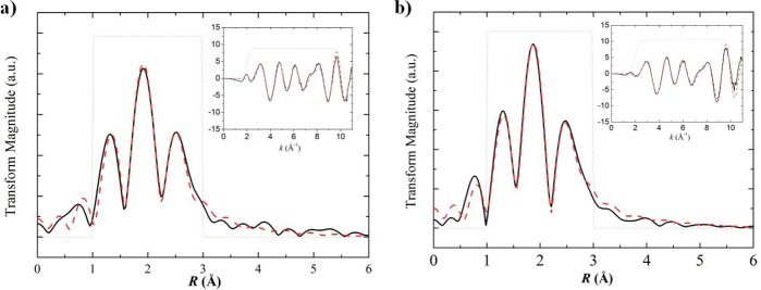
Fe K-edge EXAFS Fourier transforms and EXAFS spectra (inset) for (a) 1 and (b) UiO-66-[FeFe](dcbdt)(CO)6. Solid black lines show the experimental data, dashed red lines show the fits based on crystallographic data of 1, and dotted gray lines show the fitting window.
Table 1. First Neighboring Atom Bond Lengths of Simulated and Experimental Data Around Fe Center Based on Fe K-Edge EXAFS.
| bond length (Å) | X-raya | 1b | UiO-66-[FeFe](dcbdt9(CO)6b experimental |
|---|---|---|---|
| Fe–C | 1.779(12)/1.783(11) | 1.805 | 1.796 |
| Fe–C | 1.794(13)/1.807(12) | 1.820 | 1.811 |
| Fe–C | 1.812(14)/1.817(11) | 1.823 | 1.814 |
| Fe–S | 2.245(3)/2.253(3) | 2.268 | 2.283 |
| Fe–S | 2.252(3)2.268(3) | 2.269 | 2.285 |
| Fe–Fe | 2.484(3) | 2.437 | 2.435 |
Fitting data is based on single-crystal X-ray data of 1.
Based on EXAFS fitting (red dashed line in Figure 4).
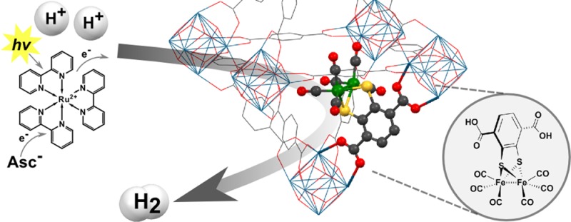
Having observed that PSE could be used to incorporate complex 1 into a robust MOF, we explored the suitability of this material as a catalyst in photochemical hydrogen production schemes. Thus, UiO-66-[FeFe](dcbdt)(CO)6 was suspended in a 1.0 M acetate buffer solution of [Ru(bpy)3]2+ photosensitizer (0.5 mM), and ascorbate electron donor (100 mM) at pH 5. As depicted in Figure 6, the projected sequence for photocatalytic proton reduction by UiO-66-[FeFe](dcbdt)(CO)6 commences with the reductive quenching of photoexcited [Ru(bpy)3]2+ by the electron donor ascorbate with a rate constant of 1 × 10⁷ M–1 s–1.45 Following the analysis of Schmehl et al.,45 14% of *[Ru(bpy)3]2+ excited states can be expected to form the [RuII(bpy)2(bpy)•–]+ reductant ([ascorbate] = 0.1 M; τ(*[Ru(bpy)3]2+) = 500 ns). Charge recombination between photogenerated [Ru(bpy)3]+ and oxidized ascorbate can be expected to occur close to the diffusion limit45 and will compete with the productive heterogeneous electron transfer (ET) between [Ru(bpy)3]+ and UiO-66-[FeFe](dcbdt)(CO)6. The driving force for the ET can be estimated at ∼300 mV from the electrochemically obtained reduction potentials, assuming that the reduction potential of the Fe2 site in UiO-66-[FeFe](dcbdt)(CO)6 is similar to that obtained for complex 1 in solution. From solution studies, it is well established that the electrochemical reduction of 1, and its bdt derivative 2, is a two-electron process due to inverted electrochemical potentials. Assuming that the Fe2 complex in UiO-66-[FeFe](dcbdt)(CO)6 shows similar reductive chemistry as complex 2 in solution, the driving force for electron transfer from a second photogenerated [Ru(bpy)3]+ to the previously produced monoreduced Fe2 site in the MOF will be even >300 mV. The dianionic Fe2 site 12– will then combine with two protons to form hydrogen. A second plausible pathway to 12– is through disproportionation of two singly reduced 1– in the MOF. This disproportionation is thermodynamically feasible as evidenced by the inverted electrochemical potentials of the 1/1– and 1–/12– couples.
Figure 6.

Reaction scheme for the photocatalytic reduction of protons.
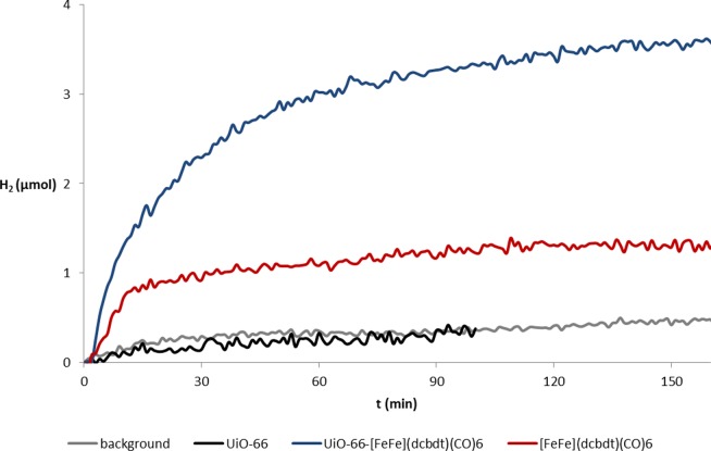
As demonstrated in Figure 7, UiO-66-[FeFe](dcbdt)(CO)6 is indeed a proton reduction catalyst. Under the reaction conditions described above, hydrogen production is observed and can be quantified with a hydrogen specific solid-state sensor (see ESI for details). It is thus clear that heterogeneous electron transfer between photogenerated [Ru(bpy)3]+ and UiO-66-[FeFe](dcbdt)(CO)6 can compete with homogeneous charge recombination with oxidized ascorbate. The Fe2 sites within the MOF can be reduced in a light-driven reaction and are themselves catalysts for the reduction of protons to molecular hydrogen. As the rate of electron transfer from photogenerated [Ru(bpy)3]+ decreases exponentially with distance, it can be assumed that only Fe2 sites that reside within a few nm from the surface of the MOF particles will be viable acceptor sites. The de facto concentration of operating catalysts in the MOF may thus be substantially smaller than the total concentration of 1 in the MOF. Comparing the activity of UiO-66-[FeFe](dcbdt)(CO)6 with that of a homogeneous reference system that contains complex 1 at concentrations similar to the total amount of Fe2 complex in UiO-66-[FeFe](dcbdt)(CO)6 shows that the activity of the former is not only preserved but actually exceeds that of the latter, both in terms of initial rate as well as overall amount of produced hydrogen.46 Control experiments without UiO-66-[FeFe](dcbdt)(CO)6 or with unmodified UiO-66 (which does not contain [FeFe](dcbdt)(CO)6) do not show meaningful amounts of hydrogen generation (Figure 7).
Figure 7.
Photocatalytic hydrogen production in the presence of UiO-66-[FeFe](dcbdt)(CO)6 (blue trace, 5 mg MOF, ∼0.59 μmol catalyst), complex 1 (red, ∼0.59 μmol), UiO-66 (black, 5 mg MOF), and background (gray). Conditions: 1 M acetate buffer pH 5, 100 mM ascorbic acid, 0.5 mM [Ru(bpy)3]2+. Light source: Blue LED 470 nm. H2 content was detected with an HY-optima 740 H2-sensor.
Quantitative comparison between the homogeneous and heterogeneous hydrogen production systems must be done with great care, as hydrogen production in both systems is not limited by an intrinsic step of the catalytic cycle but by insufficient photoproduction of the [RuII(bpy)2(bpy)•–]+ reductant.45 Nevertheless, Figure 7 clearly shows that the heterogeneous system outperforms the homogeneous one both in overall hydrogen production as well as initial rate. As shown in a recent study, the photoproduction of [RuII(bpy)2(bpy)•–]+ is not strongly influenced by homogeneous complex 2(39) and probably also not by UiO-66-[FeFe](dcbdt)(CO)6. The amount of available reductant can thus considered to be comparable in both systems. Also, the heterogeneous ET rate constant kET,het in Figure 6 is presumably not higher than the corresponding kET,hom in the homogeneous reference system. Therefore, the reasons for the superior catalytic performance of UiO-66-[FeFe](dcbdt)(CO)6 compared to that of the homogeneous reference system must be due to differences in the catalyst. A trivial but nevertheless important rationale for the increased hydrogen production yield in the MOF is the stabilization of the catalyst when inside the framework. Supporting this notion, it was found that UiO-66-[FeFe](dcbdt)(CO)6 recovered after 1 h of photocatalysis still shows the characteristic CO bands in the IR spectrum (Figure S10). In contrast, and in accordance with published work,39 complex 1 decomposes under identical photocatalysis conditions, as evidenced by the lack of any IR signals in the typical CO region.
As for all photochemical reduction schemes based on [Ru(bpy)3]2+, one-electron photochemistry needs to be coupled to a two-electron catalytic process. With the limited availability of reductant, most productive ET events will produce singly reduced Fe2 sites (1–), while dianionic Fe2 species (12–) are unlikely to be formed by an encounter with a second equivalent of [RuII(bpy)2(bpy)•–]+ due to the low concentrations of both species. As discussed above, it is thermodynamically feasible that two 1– sites disproportionate to form the catalytically active 12– site that reacts with two protons to form hydrogen. Disproportionation as well as protonation needs to occur before the reduced species recombine with oxidized ascorbate. Here, the Fe2 site in UiO-66-[FeFe](dcbdt)(CO)6 has an undisputable advantage over the homogeneous system, as its incorporation into the MOF spatially protects from unproductive charge recombination. Moreover, the presence of many Fe2 sites within the MOF may promote disproportionation as soon as two monoreduced sites are present. It is these kinetic advantages that explain the higher initial hydrogen production rates in UiO-66-[FeFe](dcbdt)(CO)6.
Conclusion
We employed PSE as an efficient and mild approach to obtain the first MOF that contains a multinuclear, organometallic, nonprecious-metal-based proton reduction catalyst. The resulting UiO-66-[FeFe](dcbdt)(CO)6 is a hybrid material that combines the advantages of molecular catalysts with a highly ordered and stable inorganic support. [FeFe](dcbdt)(CO)6 (1) is among the most complex structure that has ever been introduced into a MOF, and its presence and molecular integrity within the UiO-66 framework could be confirmed by EXAFS, FTIR, and other methods. UiO-66-[FeFe](dcbdt)(CO)6 exhibits high efficiency for photochemical hydrogen evolution, exceeding that of the homogeneous reference system in terms of rate and total hydrogen production yield. Incorporation of the Fe2 complex in UiO-66-[FeFe](dcbdt)(CO)6 results in a higher stability under the photocatalysis conditions, protects reduced species from nonproductive charge recombination, and may promote disproportionation reactions to produce catalytically active dianion 12–.
Acknowledgments
This work was supported by the Swedish Research Council, the Swedish Energy Agency, the Knut & Alice Wallenberg Foundation, the Austrian Science Fund (FWF) with an Erwin-Schrödinger fellowship for A.O. (J 3193-N17), and a grant from the National Science Foundation, Division of Materials Research (DMR-1262226). The X-ray absorption spectroscopy data were collected at Advanced Photon Source in Argonne National Laboratory on beamline 9-BM through the general user proposal program. We thank JaeWook Shin and Prof. Shirley Meng (Department of Nanoengineering, U.C. San Diego) for assistance in fitting the XAS data.
Supporting Information Available
Experimental details, and additional characterizations. This material is available free of charge via the Internet at http://pubs.acs.org.
Author Contributions
§ These authors contributed equally.
The authors declare no competing financial interest.
Supplementary Material
References
- Zou Z.; Ye J.; Sayama K.; Arakawa H. Nature 2001, 414, 625. [DOI] [PubMed] [Google Scholar]
- Maeda K.; Teramura K.; Lu D.; Takata T.; Saito N.; Inoue Y.; Domen K. Nature 2006, 440, 295. [DOI] [PubMed] [Google Scholar]
- Wang X.; Maeda K.; Thomas A.; Takanabe K.; Xin G.; Carlsson J. M.; Domen K.; Antonietti M. Nat. Mater. 2009, 8, 76. [DOI] [PubMed] [Google Scholar]
- Fujishima A.; Honda K. Nature 1972, 238, 37. [DOI] [PubMed] [Google Scholar]
- McGarrah J. E.; Kim Y. J. H., M.; Eisenberg R. Inorg. Chem. 2001, 40, 4510. [DOI] [PubMed] [Google Scholar]
- Frey M. ChemBioChem 2002, 3, 153. [DOI] [PubMed] [Google Scholar]
- Peter J. W.; Lanzilotta W. N.; Lemon B. J.; Seefeldt L. C. Science 1998, 282, 1853. [DOI] [PubMed] [Google Scholar]
- Tard C.; Pickett C. J. Chem. Rev. 2009, 109, 2245. [DOI] [PubMed] [Google Scholar]
- Lomoth R.; Ott S. Dalton Trans. 2009, 9952. [DOI] [PubMed] [Google Scholar]
- O’Keeffe M.; Yaghi O. M. Chem. Rev. 2012, 112, 675. [DOI] [PubMed] [Google Scholar]
- Sumida K.; Rogow D. L.; Mason J. A.; McDonald T. M.; Bloch E. D.; Herm Z. R.; Bae T.-H.; Long J. R. Chem. Rev. 2012, 112, 724. [DOI] [PubMed] [Google Scholar]
- Suh M. P.; Park H. J.; Prasad T. K.; Lim D. W. Chem. Rev. 2012, 112, 782–835. [DOI] [PubMed] [Google Scholar]
- Kreno L. E.; Leong K.; Farha O. K.; Allendorf M.; Van Duyne R. P.; Hupp J. T. Chem. Rev. 2012, 112, 1105. [DOI] [PubMed] [Google Scholar]
- Rocca J. D.; Liu D.; Lin W. Acc. Chem. Res. 2011, 44, 957. [DOI] [PMC free article] [PubMed] [Google Scholar]
- Yoon M.; Srirambalaji R.; Kim K. Chem. Rev. 2012, 112, 1196. [DOI] [PubMed] [Google Scholar]
- Eddaoudi M.; Kim J.; Rosi N.; Vodak D.; Wachter J.; O’Keeffe M.; Yaghi O. M. Science 2002, 295, 469. [DOI] [PubMed] [Google Scholar]
- Brozek C. K.; Dinca M. Chem. Sci. 2012, 3, 2110. [Google Scholar]
- Burnett B. J.; Barron P. M.; Hu C. H.; Choe W. J. Am. Chem. Soc. 2011, 133, 9984. [DOI] [PubMed] [Google Scholar]
- Cohen S. M. Chem. Rev. 2012, 112, 970. [DOI] [PubMed] [Google Scholar]
- Das S.; Kim H.; Kim K. J. Am. Chem. Soc. 2009, 131, 3814. [DOI] [PubMed] [Google Scholar]
- Tanabe K. K.; Cohen S. M. Chem. Soc. Rev. 2011, 40, 498. [DOI] [PubMed] [Google Scholar]
- Wang Z.; Cohen S. M. Chem. Soc. Rev. 2009, 38, 1315. [DOI] [PubMed] [Google Scholar]
- Lalonde M.; Bury W.; Karagiaridi O.; Brown Z.; Hupp J. T.; Farha O. K. J. Mater. Chem. A 2013, 1, 5453. [Google Scholar]
- Brozek C. K.; Dincă M. J. Am. Chem. Soc. 2013, 135, 12886–12891. [DOI] [PubMed] [Google Scholar]
- Li T.; Kozlowski M. T.; Doud E. A.; Blakely M. N.; Rosi N. L. J. Am. Chem. Soc. 2013, 135, 11688. [DOI] [PubMed] [Google Scholar]
- Zhang Z.; Zhang L.; Wojtas L.; Nugent P.; Eddaoudi M.; Zaworotko M. J. J. Am. Chem. Soc. 2011, 134, 924. [DOI] [PubMed] [Google Scholar]
- Kim M.; Cahill J. F.; Su Y.; Prather K. A.; Cohen S. M. Chem. Sci. 2012, 3, 126. [Google Scholar]
- Kim M.; Cahill J. F.; Fei H.; Prather K. A.; Cohen S. M. J. Am. Chem. Soc. 2012, 134, 18082. [DOI] [PubMed] [Google Scholar]
- Karagiaridi O.; Lalonde M. B.; Bury W.; Sarjeant A. A.; Farha O. K.; Hupp J. T. J. Am. Chem. Soc. 2012, 134, 18790. [DOI] [PubMed] [Google Scholar]
- Fei H.; Cahill J. F.; Prather K. A.; Cohen S. M. Inorg. Chem. 2013, 52, 4011. [DOI] [PubMed] [Google Scholar]
- Lee J. F., O. K.; Roberts J.; Scheidt K. A.; Nguyen S. T.; Hupp J. T. Chem. Soc. Rev. 2009, 38, 1450. [DOI] [PubMed] [Google Scholar]
- Ma L.; Abney C.; Lin W. Chem. Soc. Rev. 2009, 38, 1248. [DOI] [PubMed] [Google Scholar]
- Wang C.; deKrafft K. E.; Lin W. J. Am. Chem. Soc. 2012, 134, 7211. [DOI] [PubMed] [Google Scholar]
- Fateeva A.; Chater P. A.; Ireland C. P.; Tahir A. A.; Khimyak Y. Z.; Wiper P. V.; Darwent J. R.; Rosseinsky M. J. Angew. Chem., Int. Ed. 2012, 51, 7440. [DOI] [PubMed] [Google Scholar]
- Wang J.-L.; Wang C.; Lin W. ACS Catal. 2012, 2, 2630. [Google Scholar]
- Wang C.; Wang J.-L.; Lin W. J. Am. Chem. Soc. 2012, 134, 19895. [DOI] [PubMed] [Google Scholar]
- Wang C.; Xie Z.; deKrafft K. E.; Lin W. J. Am. Chem. Soc. 2011, 133, 13445. [DOI] [PubMed] [Google Scholar]
- Felton G. A. N.; Vannucci A. K.; Chen J.; Lockett L. T.; Okumura N.; Petro B. J.; Zakai U. I.; Evans D. H.; Glass R. S.; Lichtenberger D. L. J. Am. Chem. Soc. 2007, 129, 12521. [DOI] [PubMed] [Google Scholar]
- Streich D.; Astuti Y.; Orlandi M.; Schwartz L.; Lomoth R.; Hammarstrom L.; Ott S. Chem.—Eur. J. 2010, 16, 60. [DOI] [PubMed] [Google Scholar]
- Seidel W. W.; Hahn F. E.; Lügger T. Inorg. Chem. 1998, 37, 6587. [DOI] [PubMed] [Google Scholar]
- Sellmann D.; Becker T.; Knoch F. Chem. Ber. 1996, 129, 509. [Google Scholar]
- Kim M.; Cohen S. M. CrystEngComm 2012, 14, 4096. [Google Scholar]
- Yang Q.; Wiersum A. D.; Llewellyn P. L.; Guillerm V.; Serred C.; Maurin G. Chem. Commun. 2011, 47, 9603. [DOI] [PubMed] [Google Scholar]
- Shan B.; Baine T.; Ma X. A. N.; Zhao X.; Schmehl R. H. Inorg. Chem. 2013, 52, 4853. [DOI] [PubMed] [Google Scholar]
- Assuming a 15% integration of 1 in the MOF, 5 mg of UiO-66-[FeFe](dcbdt)(CO)6 contain 0.59 μmol of 1. The solution experiments were thus conducted with 0.59 μmol of 1 dissolved in pH = 5 buffer solution (see also ESI).
Associated Data
This section collects any data citations, data availability statements, or supplementary materials included in this article.


