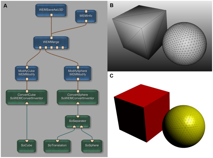
Figure 4. Example of a more complex application network.
(A) This example network simulates a complex image processing chain (read from bottom to top). The network generates an Open Inventor Scene with a cube and a sphere as “segmentation results” (B). The two objects are then converted into WEM patches (SoWEMConvertInventor modules) and the properties (names and colors) are set (WEMModify modules). Finally the two WEM patches are merged into one WEM and afterwards written into a U3D file. The result is displayed on the bottom right (C). A file containing this network is provided as File S1.

