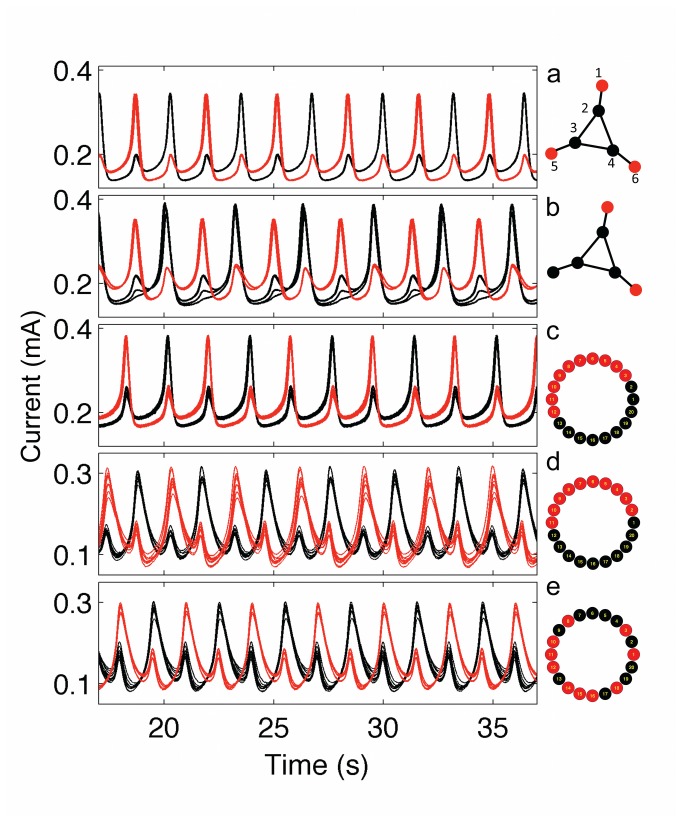
Figure 4. Cluster dynamics of relaxation oscillators on extended triangle and NLR networks.
Left panels: current vs time of the electrodes. Right panels: coupling topology and schematic of synchronization patterns. a: (3–3) two-cluster state in which the synchronized center (2–4) oscillators (black) are in anti-phase configuration to the periphery (1,5,6) oscillators (red). V=1290 mV, R ind= 1200 Ω, R= 1500 Ω. b: (2,4) two-cluster states in anti-phase synchronization. V=1300 mV, R ind=1200 Ω, R= 1000 Ω. c: (10–10) condensed two-cluster cluster state with the NLR network. Oscillators in one half of the circle (red) are anti-phase synchronized with oscillators in the other half (black). V=1335 mV, R ind=1200 Ω, R=5000 Ω. d: (10–10) two-cluster condensed state with combined resistive-capacitive coupling. V=1190 mV, R ind= 1000 Ω, C=33 μΦ. e: (10–10) flip-flop two-cluster synchronized state in which the red elements are anti-phase synchronized with black elements. V=1190 mV, R ind= 1000 Ω, C=33 μΦ.

