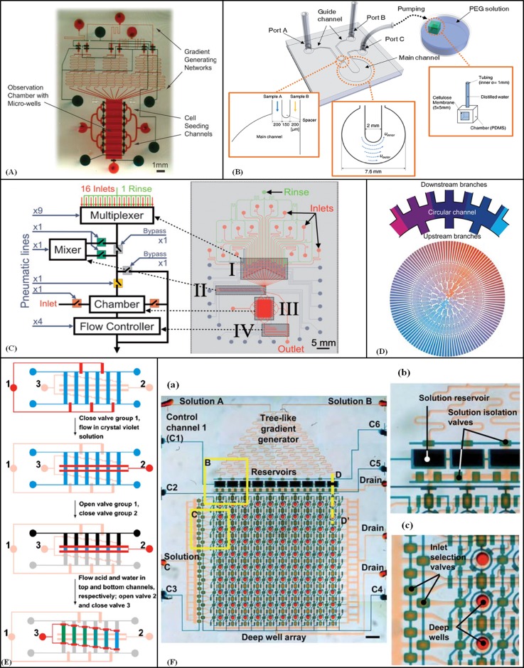
Figure 4.
Gradient-generating devices based on streams of laminar flow. (A) A device composed of two microfabricated PDMS layers containing gradient generating network, cell seeding channels, observation chamber and control valves. Reproduced by permission from Wang et al., Lab Chip 8, 227–237 (2008). Copyright 2008 by The Royal Society of Chemistry. (B) Schematic of chemical and mechanical gradients generator device with a circular main channel. Reproduced by permission from Park et al., Lab Chip 9, 2194–2202 (2009). Copyright 2009 by The Royal Society of Chemistry. (C) Multipurpose and computer-controlled microfluidic perfusion device. Reproduced by permission from Cooksey et al., Lab Chip 9, 417–426 (2009). Copyright 2009 by The Royal Society of Chemistry. (D) Fluid distribution with the branch channels and the circular channels of the 2-inlet radial gradient generator. Reproduced by permission from Yang et al., Lab Chip 11, 3305–3312 (2011). Copyright 2011 by the Royal Society of Chemistry. (E) Operation of the microchip to generate stepwise gradient. Valve channels groups are shown (red = closed and pink = open). The fluidic channels are in the shape of a ladder (blue, grey, and black colours stand for different solutions). Reprinted with permission from Dai et al., Biomicrofluidics 4, 1–14 (2010). Copyright 2010 American Institute of Physics. (F) (a) 2D microfluidic combinatorial dilution device with a tree-like gradient generator (TLGG) and a microfluidic active injection system that mixes two input solutions and pre-filled solutions in wells to fill array of deep wells with different relative concentrations. (b) and (c) Enlarged view of reservoirs and deep wells. Reproduced by permission from Jang et al., Lab Chip 11, 3277–3286 (2011). Copyright 2011 by The Royal Society of Chemistry.

