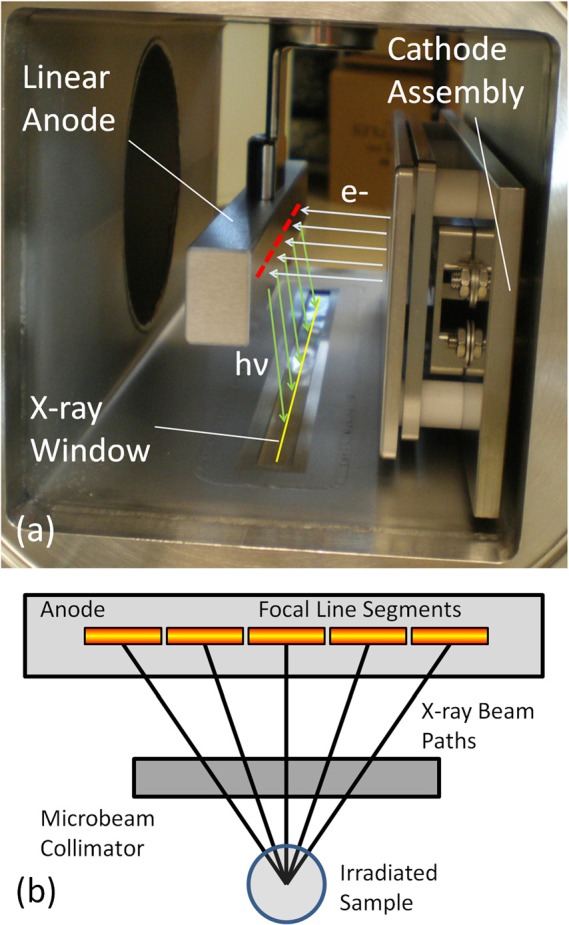
Figure 1.

(a) Photograph detailing the basic structure inside the compact microbeam irradiator Also shown are indicators for electron trajectories from the cathode assembly (light blue), the location of the segmented focal line on the anode (red), X-ray photon trajectories from the anode (light green), and the projected focal line image on the window (yellow). (b)Diagram (as seen from cathode assembly) showing how the multiple line segments produce microbeam paths that irradiate a sample from different angles. For another illustration of how microbeams are created from our source, see Figure 4b.
