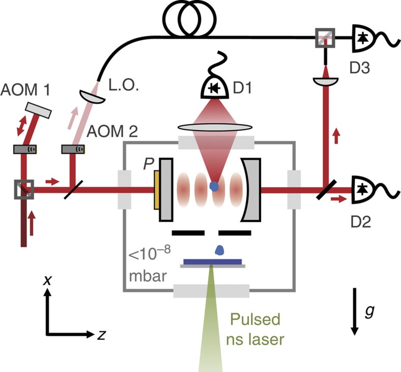
Figure 1. Experimental setup for cavity cooling in a high-vacuum environment.
The fibre laser beam (1,560 nm) is double passed in AOM1 (2 × 40 MHz) to stabilize the laser frequency to the cavity on short timescales. Over long timescales, the piezoelectric transducer P locks the cavity to the laser frequency. A part of the stabilized beam is split off and frequency-shifted by AOM2 to serve as the local oscillator beam (LO). The other part (1 mW) is coupled into the high-finesse cavity inside a high-vacuum chamber (<10−8 mbar). The cavity has a finesse of 3 × 10⁵, a waist of w=65 μm at the centre and consists of one flat and one curved mirror (radius of curvature: 25 mm). The transmitted intensity, which is a direct measure for the intracavity power, is detected by photodiode D2. A part of the transmitted intensity is fibre coupled, overlapped with the local oscillator beam and detected by D3. The phase of the resulting beating signal allows us to extract information about the cavity phase. A pulsed ns-laser (532 nm, 15 mJ) is focused onto a 0.5 mm thick silicon wafer to create and launch slow silicon nanoparticles. The wafer is attached to the top of a quartz plate. To avoid contamination of the cavity mirrors, the particles travel through a 1-mm aperture before they enter the cavity mode. Light scattered from within the cavity is focused onto the photodiode D1.

