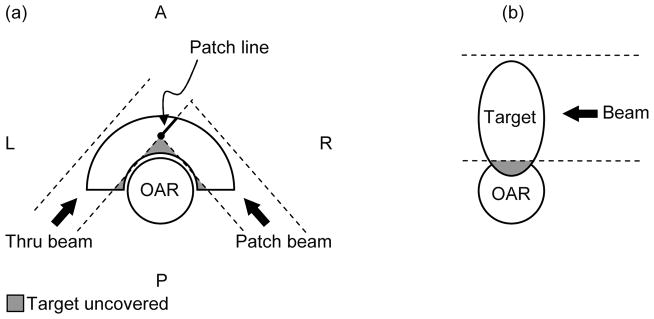
Figure 1.

The two geometries of target volumes and organs at risk that represent challenges for proton therapy, even when the field patching technique is employed. (a) Concave target partially surrounding convex OAR. For this illustration only PA and P-lateral oblique fields are allowed. The dashed lines represent the projection of the collimator opening and the grey shaded areas identify the portions of the target left uncovered. (b) OAR partially surrounding the target or target infiltrating the OAR. A = Anterior; P = Posterior; L = Left Lateral; R = Right Lateral. AP identifies the anteroposterior axis, LR the left-right lateral axis. The third major anatomical axis is the superior-inferior (SI).
