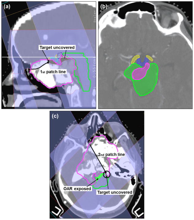
Figure 3.
Skull-base chondrosarcoma. Target in pink, brainstem in green, chiasm in cyan, hypothalamus in blue and right optical tracks in yellow. (a) Sagittal view of the first patch combination consisting of a superior-anterior beam (gantry/couch angle 70°/270°) and a left-superior-anterior beam (70°/350°). (b) Axial view corresponding to the plane identified by the horizontal solid white line in (a). (c) Axial view of the second patch combination consisting of a left-posterior beam (150°/0°) and a right-posterior beam (225°/0°). The other beams are 270°/0°, 80°/0°, 210°/0°, 280°/65° and 270°/10°. Note: for the IMPT plan the following 4 beams were used, i.e., 270°/0°, 80°/0°, 210°/0°, 280°/65°.

