Figure 4.

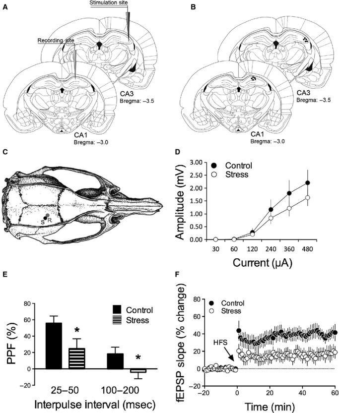
Single-channel recordings. (A) A schematic of the single-channel experimental design with stimulating electrode placed in dorsal CA3 and recording electrode placed in dorsal CA1. (B) Representative electrode placements in the two regions of interest as indicated by black dots. (C) A rendering of a rat skull and the positions of the bored holes for the placements of the stimulating (S) and the recording (R) electrodes. Adapted from Paxinos and Watson (1997). (D) Input/output curves for CA1 for control and stressed rats obtained prior to the initial PPF recordings. (E) Pretetanus PPF values for the averaged 25–50 msec and 100–200 msec interpulse intervals in CA1 for control (solid bars) and stressed (striped bars) rats. (F) High-frequency stimulation (HFS)-induced long-term potentiation (LTP) is present in CA1 (black circle; n = 6) under control conditions and is disrupted under stressful conditions (open circles; n = 5).
